Caution – Cashco 1000 HP Differential User Manual
Page 7
7
IOM-1000HP-Dif fer en tial
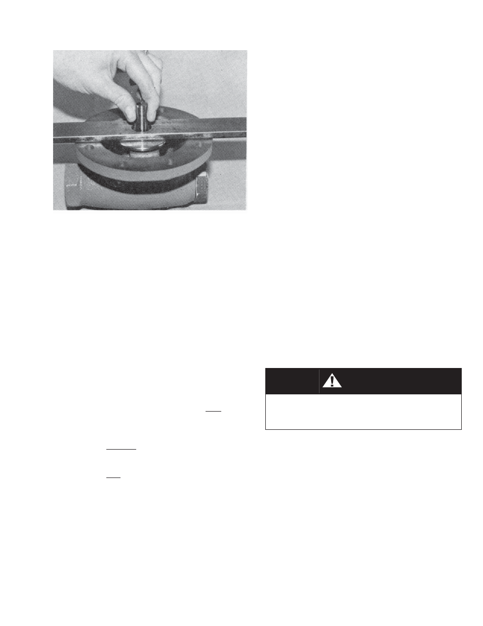
3. Follow procedure “Sub-Section B., Di a phragm
Re place ment” to the point of removing
diaphragm(s) (20), Step 13. Remove di a-
phragm gasket (19) and pusher plate stud
gasket (12). Obtain a fl at 12" x 1-1/2" x 1/4"
(15 mm x 40 mm x 6 mm) plate bar with a
3/4" (20 mm) hole drilled in the center. “Hook”
the pusher plate stud (13) into the rocker arm
(14) prongs properly. Pull fi rmly up on the
pusher plate stud (13) to ensure that all slack
is removed from the mechanism and that the
piston (24) is seated fi rmly. Relax the pulling
and place the fl at bar over the pusher plate
stud (13) with the stud (13) passing through
the hole of the bar. Again, pull fi rmly up to
remove mech a nism slack. One of three po si-
tions will be reached:
a. Diaphragm setting too high. Pusher plate
stud (13) will lift the fl at bar over 0.020"
(.51 mm).
b. Diaphragm setting acceptable. Bar lifted
between 0.010"–0.020" (.25–.51 mm).
c. Diaphragm setting too low. Bar lifted
less than 0.010" (.25 mm), or failed to be
lifted.
4. The castle style stud nut (10) has six locations
per revolution to align the stud nut (10) slots
with the drilled hole through the pusher plate
stud (13). Each stud nut (10) slot represents
a movement up/down of 0.010" (.25 mm).
NOTE: The ideal diaphragm setting is 0.015"
(.4 mm) high. Better performance is usually
ob tained when the diaphragm is at this value,
rather than a lower level. As the measuring of
a thou sandths of an inch is diffi cult with such
a pro ce dure, it is rec om mend ed that the “null”
position be found where the diaphragm(s) (20)
is fl ush with the body (1) fl ange (bar approxi-
mately at 0.000"). Remove the pusher plate
stud (13), rotate the stud nut (10) one or two
slots CCW to bring the setting to 0.010–0.020"
(.25–.51 mm) high.
5. Place cotter pin (15) through the slot, bend
over ends.
6. Continue reassembly per Sub-Section B,
Di a phragm Replacement, Step 16.
E. Trim Removal and Replacement:
1. Install body (1) horizontally in a vise with the
spring chamber (2) directed upwards, and the
body (1) held at the outlet end.
2. Use a box end wrench, or socket, with a lever
length of at least 24 inches (610 mm), and
place over the hex surfaces of the cylinder
(21). The wrench should be rapped with a
hammer to loosen.
3. Continue to unscrew cylinder (21) until re-
moved. The piston (24) and piston collar (23)
should come out by gravity with the cylinder
(21) removal.
CAUTION
Take precautions not to allow the piston (24)
to fall from within the cylinder (21); tip cylinder
with hex end down.
4. If an Option 1000-17 piston spring (30) is uti-
lized, it also should be removed and re placed
at trim re place ment.
5. Inspect inside surface of cylinder (21) at four
points:
a. Seat (21.2) ring. Check for erosion/wear
on seat ing surfaces. If wear is ex ces sive,
consider utilizing Option 1000-15, stellited
seat surface.
b. Seat (21.2). Check for wire drawing
be tween cylinder (21.1) and seat (21.2)
where pressed in. If wear exists here, an
Option 1000-14, integral seat, should be
utilized as a replacement.