Cashco P1 User Manual
Model p1, Single stage pressure reducing regulator, I. description and scope
INSTALLATION, OPERATION & MAINTENANCE MANUAL (IOM)
IOM-P1
11/13
SECTION I
I. DESCRIPTION AND SCOPE
The Model P1 is a pressure reducing regulator used to control downstream (outlet or P
2
) pressure. Sizes are 1/4"
and 3/8" (DN8 and DN10) FNPT or 1/2" (DN15) with Tri-Clamp connections. The unit is suitable for gaseous or liquid
services. Refer to Technical Bulletin P1-TB for design conditions and selection recommendations.
SECTION II
II. INSTALLATION
MODEL P1
SINGLE STAGE
PRESSURE REDUCING REGULATOR
1. An inlet block valve should always be installed.
2. If service application is continuous such that
shut down is not readily accomplished, it is rec-
ommended that an inlet block valve, outlet block
valve, and a manual bypass valve be installed.
3. Pipe unions should be installed to allow removal
from piping.
4. An outlet pressure gauge should be located ap-
proxi mately ten pipe diameters downstream, and
within sight.
5. All installations should include a downstream re-
lief de vice if the inlet pressure could exceed the
pres sure rating of any downstream equip ment or
the maximum outlet pressure rating of the unit.
6. Clean the pip ing of all foreign material including
chips, welding scale, oil, grease and dirt before
installing the reg u la tor. Strainers are rec om -
mend ed.
7. In plac
ing thread seal ant on pipe ends pri or to
en gage ment, ensure that excess material is
CAUTION
Installation of adequate overpressure pro tec tion
is recommended to pro tect the reg u la tor from
over pres sure and all down stream equip ment from
dam age in the event of regulator failure.
re moved and not allowed to enter the regulator
upon startup.
8. Flow Direction: Install so the flow direction
match es the inlet stamp on the main regulator
body (1).
9. For best performance, install in well drained hori-
zon tal pipe.
10. Basic Regulator - (Refer to Figure 2, Model P1):
Regulator may be rotated around the pipe axis
360°. Recommended position is with aluminum
knob (4) ver ti cal upwards.
11. Regulators are not to be buried un der ground.
12. For insulated piping systems, recommendation is
to not insulate regulator.
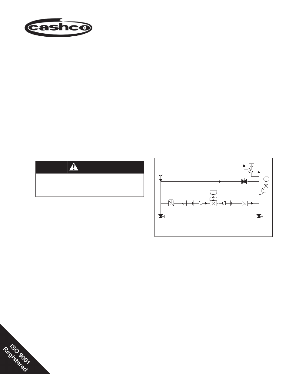
Recommended Piping Schematic
For Pressure Reducing Station
P
1
Outlet
@P
2
SRV
Supply
@P
1
Bypass
Model P1
Reducing
Regulator
Blowdown-Drain
Blowdown-Drain