Cashco HP User Manual
Model hp, Pressure re duc ing regulator
INSTALLATION, OPERATION & MAINTENANCE MANUAL (IOM)
IOM-HP
12-13
MODEL HP
PRESSURE RE DUC ING REGULATOR
SECTION I
I. DESCRIPTION AND SCOPE
The Model HP is a heavy duty, high pressure reducing regulator used to control downstream (outlet or P
2
) pres sure.
Sizes are 1/2", 3/4", 1" and 1-1/2" (DN15, 20, 25 and 40). With proper trim utilization, the unit is suit able for liquid and
gaseous service. Refer to Technical Bulletin HP-TB for design conditions and selection rec om men da tions. NOT FOR
STEAM SERVICE.
SECTION II
II. INSTALLATION
1. An inlet block valve should always be installed.
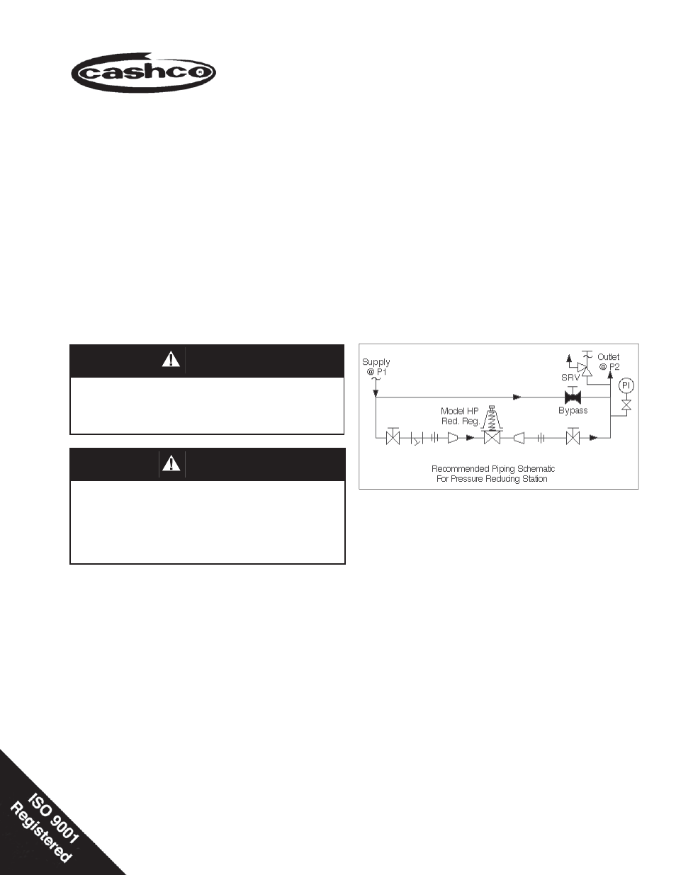
2. If service application is continuous such that shut down
is not readily accomplished, it is rec ommended that
an inlet block valve, outlet block valve, and a manual
bypass valve be installed.
3. Pipe unions should be installed to allow removal from
piping.
4. An outlet pressure gauge should be located ap prox-
i mately ten pipe diameters downstream, and within
sight.
5. All installations should include a downstream re lief
de vice if the inlet pressure could exceed the pres sure
rating of any downstream equip ment or the maximum
outlet pressure rating of the unit.
6. Clean
the
pip
ing of all foreign material including chips,
welding scale, oil, grease and dirt before installing the
regulator. Strainers are rec om mend ed.
7. In
plac
ing thread seal ant on pipe ends pri or to en-
gage ment, ensure that excess material is re moved
and not allowed to enter the regulator upon startup.
8. Flow Direction: Install so the fl ow direction match es
the arrow cast on the main regulator body.
9. Basic Regulator - (Refer to Figure 1): Regulator may
be rotated around the pipe axis 360°. Rec om mend ed
position is with spring chamber ver ti cal upwards. Orient
such that the spring chamber vent hole does not collect
rainwater or debris.
10. Regulators are not to be direct buried un der ground.
11. For insulated piping systems, recommendation is to not
insulate regulator.
CAUTION
For welded installations, all internal trim parts, seals
and diaphragm(s) must be removed from reg u la tor
body prior to welding into pipeline. The heat of
fusion welding will dam age non-metallic parts if
not re moved. NOTE: This does not apply to units
equipped with extended pipe nip ples.
CAUTION
Installation of adequate overpressure pro tec tion is
recommended to pro tect the reg u la tor from overpres-
sure and all down stream equip ment from damage
in the event of regulator failure.