Cashco 2171 User Manual
Back pressure / relief regulators
MODELS 1171 AND 2171
BACK PRESSURE / RELIEF REGULATORS
SECTION I
I. DESCRIPTION AND SCOPE
The instructions in this manual will refer to both models, unless otherwise stated.
INSTALLATION, OPERATION & MAINTENANCE MANUAL (IOM) IOM-1171/2171
12-13
SECTION II
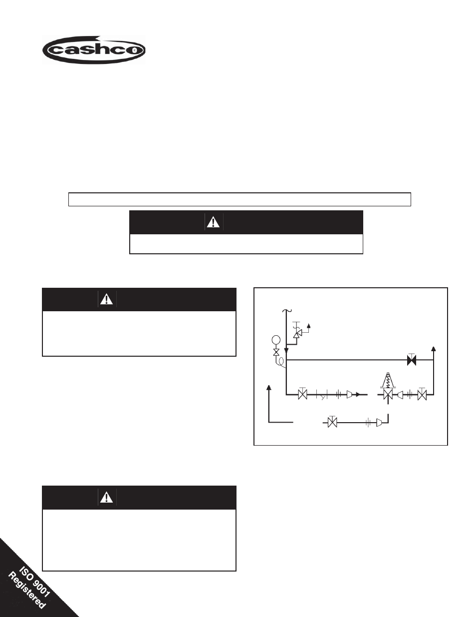
Recommended Piping Schematic For Back Pressure/Relief Station
Models 1171/2171
BP/Relief Regulator
Models 1171 and 2171 are back pressure/relief regulators used to control upstream (inlet or P
1
) pressure. Sizes
are 1/4" and 3/8" (DN8 and DN10). The Model 2171 is also available in 1/2" (DN15) size. The 1171 is a bronze
bodied unit; the 2171 incorporates a stainless steel body. With proper trim utili za tion, both units are suitable for
liquid, gaseous and steam service (the 2171 can also be used with various chemi cals). Refer to Tech ni cal Bul le tins
1171-TB and 2171-TB for specifi c design conditions and selection rec om men da tions.
1. An inlet block valve should always be in stalled.
2. If service application is continuous such that
shut down is not readily accomplished, it is rec-
ommended that an inlet block valve, outlet block
valve, and a manual bypass valve be installed.
3. Pipe unions should be installed to allow removal
from piping.
4. An inlet pressure gauge should be located ap prox-
i mately ten pipe diameters upstream, and within
sight. An outlet pressure gauge is op tion al.
II. INSTALLATION
5. All installations should include an upstream relief
device if the inlet pressure could exceed the pres-
sure rating of any equip ment or the max i mum inlet
pressure rating of the unit.
6. Clean piping of all foreign material including chips,
welding scale, oil, grease and dirt before installing
the regulator. Strainers are recommended.
7. In placing thread sealant on pipe ends prior to en-
gagement, assure that excess material is re moved
and not allowed to enter regulator upon startup.
Supply
@ P1
SRV
System
P1
P1
P2
Dis charge
CAUTION
For welded installations, all internal trim parts, seals and
diaphragm(s) must be removed from reg u la tor body prior
to welding into pipeline. The heat of fusion welding will
dam age non-metallic parts if not re moved. NOTE: This does
not apply to units equipped with extended pipe nip ples.
CAUTION
This is not a safety device and must not be sub sti tut ed for a code
approved pressure safety relief valve or rupture disc.
CAUTION
The maximum inlet pressure is equal to 1.5 times the
larger number of the stated range spring on the name-
plate, and is the rec om mend ed "upper op er a tive limit" for
the sens ing diaphragm. Higher press ures could dam age
the di a phragm. (Field hydro static tests fre quent ly destroy
dia phragms. DO NOT HYDRO STATIC TEST THRU AN
IN STALLED UNIT; ISO LATE FROM TEST.)