Warning – Cashco 1000 HP Differential User Manual
Page 4
4
IOM-1000HP-Dif fer en tial
SECTION VI
WARNING
(19) is not used with a composition (soft)
diaphragm.)
NOTE: The text hereafter will refer to:
a. The -1+8 double di a phragm op tion al
con struc tion (-1+6 single di a phragm
con struc tion is sim i lar. Text regarding
com po si tion diaphragm(s) (20) applies
only to -1+6 op tion). Text portions deal-
ing with body spacer (42), diaphragm
spacer (41) and sep a ra tion of total di a-
phragm (20) quantity into two “stacks”
applies only to -1+8 option.
b. The “pusher plate and stud” (13) as a
single part for 1/2" – 1-1/4" sizes and
as two separate parts, a “pusher plate”
(5) and a “pusher stud” (13) , for 1-1/2"
and 2" sizes.
7. Pry up the diaphragm(s) (20) and diaphragm
gas ket (19) around the perimeter of the body (1)
di a phragm fl ange to ensure the diaphragm(s)
(20) are not “stick ing”. (Di a phragm gasket
(19) is not used with a com po si tion (soft)
diaphragm.)
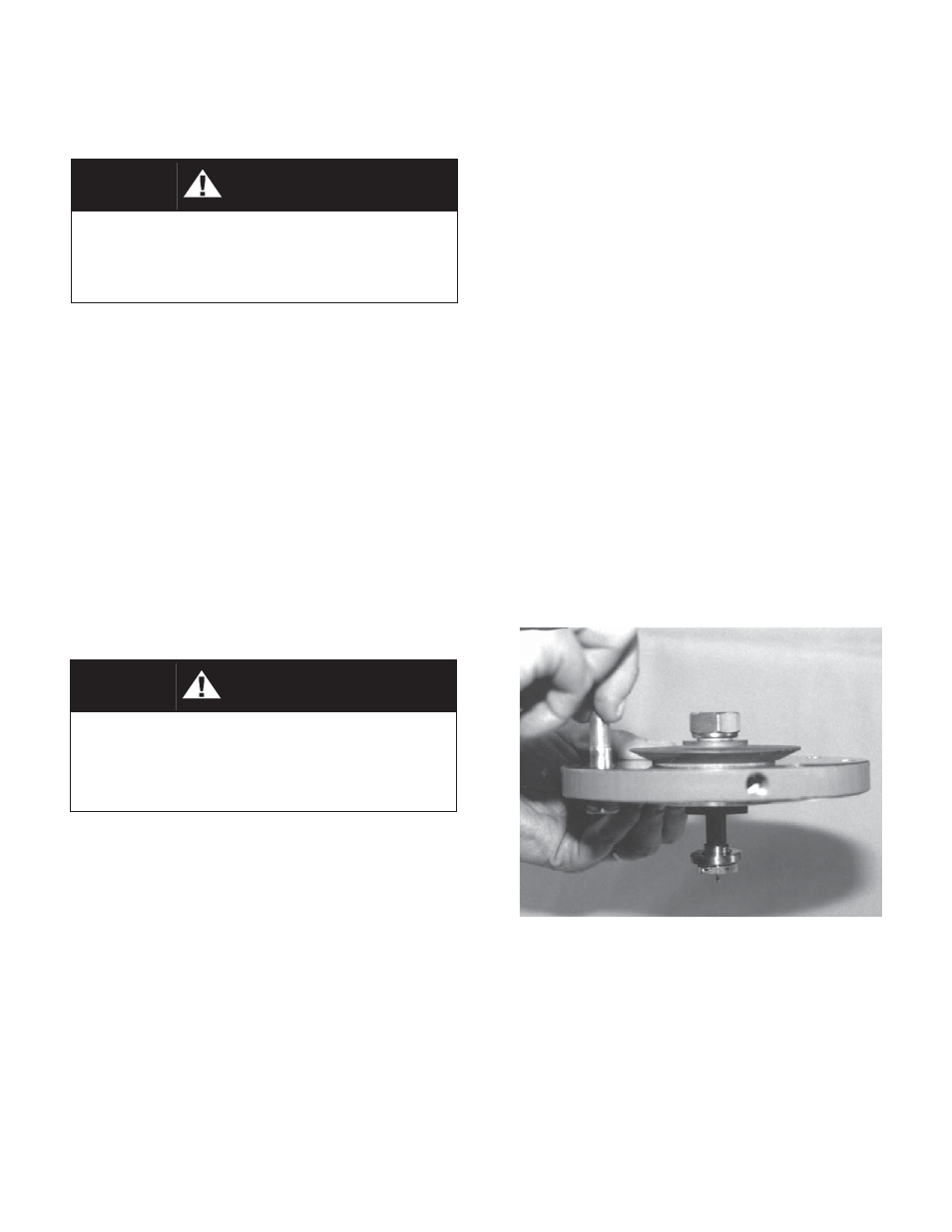
8. Remove diaphragm subassembly by sliding
the push er plate and stud (13), body spacer
WARNING
2. Remove closing cap (31). Relax range spring
(27) by turning adjusting screw (6) CCW until
re moved from spring chamber (2).
3. Paint or embed a match mark between body
casting (1), spring chamber casting (2), and
body spacer (42) along fl anged area.
4. Remove all diaphragm fl ange nuts (9) and
bolts (8). Remove nameplate (28).
5. Remove spring chamber (2), spring button (4)
and range spring (27).
6. Pry up the diaphragm(s) (20) and diaphragm
gasket (19) around the perimeter of the spring
chamber (2) fl ange to ensure the diaphragm(s)
(20) are not “sticking”. (Di a phragm gasket
VI. MAINTENANCE
SYSTEM UNDER PRESSURE. Prior to per form ing
any maintenance, isolate the regulator from the
system and relieve all pressure. Failure to do so
could result in personal injury.
A. General:
1. Maintenance procedures hereinafter are based
upon removal of the unit from the pipeline
where installed.
2. Owner should refer to owner’s procedures for
re mov al, handling and cleaning of reusable
parts, and dis pos al of non-reusable parts, i.e.
gaskets.
3. If desired, the gaskets may be lubricated with
a light oil provided it is com pat i ble with the
fl uid.
B.
Diaphragm
Replacement:
1. Securely install the body (1) in a vice with the
spring chamber (2) directed upwards.
SPRING UNDER COMPRESSION. Prior to re mov-
ing fl ange bolts, relieve spring compression by
back ing out the adjusting screw. Failure to do
so may result in fl ying parts that could cause
personal injury.
Diaphragm subassembly consists of items (10), (11),
(12), (13), (15), (16), (20), (41), (42) and (50). (Metal
di a phragm design.)
(42) and nut (11) in the direction of the reg u -
la tor inlet, approximately 1/2"–3/4" (15-20
mm) The pusher plate and stud (13), stud nut
(10), and stud collar (16) should dis en gage
with the rocker arm (14) slot. Lift ver ti cal ly
for di a phragm subassembly re mov al, care-
fully hold ing the assembly at its outer edge
to prevent the body spacer (42) from falling
from be tween the diaphragm(s) (20).