Cashco 1000 LP User Manual
Model 1000lp - basic pressure reducing regulator, Caution a caution b
INSTALLATION, OPERATION & MAINTENANCE MANUAL
IOM-1000LP-Basic
12-13
MODEL 1000LP - BASIC
PRESSURE REDUCING REGULATOR
SECTION I
I. DESCRIPTION AND SCOPE
The Model 1000LP is a pressure reducing regulator used to control downstream (outlet or P
2
) pressure to
levels between 1 and 30 psig (0.07-2.06 Barg). Sizes are 1/2", 3/4", and 1" (DN15, 20, and 25).
The unit is designed for liquid, gaseous or steam service with proper trim utilization, and proper jet selection.
Refer to Technical Bulletin 1000LP-TB for sizing, application and selection recommendations.
Installation, operation and maintenance manuals (IOM's) exist for the following other Model 1000 products:
1000HP-Basic
1000HP-Differential
1000HP-Cryogenic
SECTION II
II. INSTALLATION
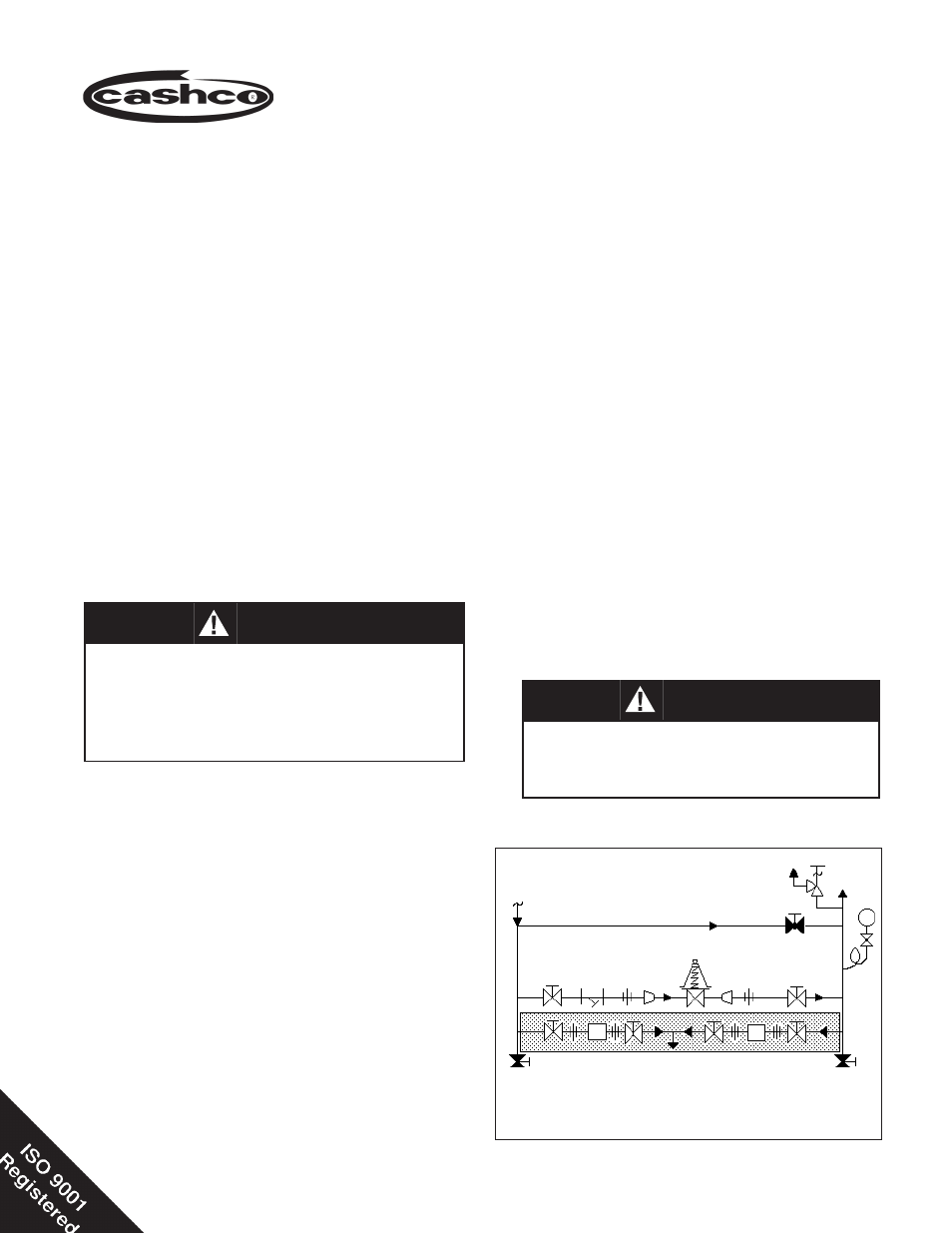
Recommended Piping Schematic
For Pressure Reducing Station
Model 1000LP
Reducing Regulator
Blowdown-Drain
Blowdown-Drain
Bypass
SRV
Outlet
@ P2
Supply
@ P1
TR
TR
PI
For welded installations, all internal trim parts,
seals and diaphragm(s) must be removed from
reg u la tor body prior to welding into pipeline. The
heat of fusion welding will dam age non-metallic
parts if not re moved. NOTE: This does not apply
to units equipped with extended pipe nip ples.
CAUTION A
CAUTION B
Installation of adequate overpressure pro tec tion
is recommended to pro tect the reg u la tor from
overpressure and all down stream equip ment
from damage in the event of regulator failure.
1. An inlet block valve should always be installed.
An outlet block valve is recommended.
2. If service application is continuous such that
shut down is not readily accomplished, it is
rec om mended that an inlet block valve and a
man u al bypass valve be installed.
3. Pipe unions must be installed to allow removal
from piping. Trim can only be changed by unit
removal from pipeline. If fl anges are utilized, a
lap joint fl ange is required on the inlet end of the
regulator to help align bolt holes as the cylinder
screws into place.
4. An outlet pressure gauge should be located
ap prox i mate ly ten pipe diameters down stream,
and with in sight.
5. All installations should include a downstream
relief de vice if the inlet pressure could exceed
the pressure rating of any downstream equip-
ment or the maximum outlet pressure rating of
the unit.