Cashco 8310HP - Differential User Manual
Nb pb qb
INSTALLATION, OPERATING AND
MAINTENANCE INSTRUCTIONS
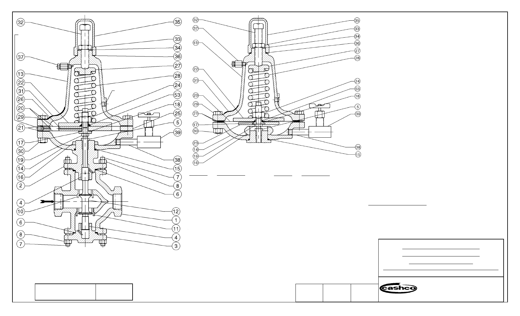
Install with arrow on body (1) pointing in direction of flow.
Install an external sensing line (1/2" O.D. tubing min.) from the 3/8" NPT
connection in needle valve (39) to a point downstream, preferably at gauge
location.
Install oil loading pressure sensing line to spring chamber (13) connec-
tion.
For long operational life with minimum maintenance, install a strainer in
the upstream line. If valve pipe line is expanded to a larger pipe line, al-
ways connect steam sensing line to the larger pipe line. To increase the
differential setting, turn the adjusting screw (32) clockwise. To decrease
the differential setting, turn the adjusting screw (32) counterclockwise.
Before disassembling the valve for maintenance work, always release the
tension on the range spring (28) by turning the adjusting screw (32) coun-
terclockwise.
For examination or replacement of diaphragms (20), remove spring cham-
ber (13). Place wrench on flats of pusher plate (17). Remove nut (24), and
pressure plate (22), then remove upper set of diaphragms (20), diaphragm
spacer (26), body spacer (25), and lower set of diaphragms (20).
For examination or replacement of plug (12), proceed as noted above,
then remove stem lock nut (19). Remove bottom flange (3) and remove
plug and stem subassembly (12). Upon reassembly make certain the dia-
phragm case (14) is pulled down tight to make metal to metal contact.
The diaphragm setting must be flush to ensure proper valve travel (with
plug against the seat, adjust the pusher plate (17) so that the gasket (18)
face of the pusher plate (17) is flush with the top of the case (14) flange
and then tighten the stem lock nut (19) by holding upper flats on the pusher
plate (17)).
STABILIZING NEEDLE VALVE – The needle valve (39) is shipped in a
full open position. If the system is unstable due to pressure fluctuations,
slowly close this valve (39) until system becomes stable. This valve (39)
should never be in a fully closed position.
Turn handle of bleeder valve (37) counterclockwise to bleed off air en-
trapped above oil to ensure stable operation.
ITEM NO.
DESCRIPTION
1
BODY
2
BONNET
3
BOTTOM FLANGE
4
GUIDE BUSHING
5
STEM BUSHING
6
BODY GASKET
7
BODY STUD
8
BODY STUD NUT
10
UPPER SEAT RING
11
LOWER SEAT RING
12
VALVE PLUG ASSEMBLY
12.1
PLUG
12.2
STEM
12.3
PIN (GROOVE)
13
SPRING CHAMBER
14
DIAPHRAGM CASE
15
O-RING
16
BONNET NUT
17
PUSHER PLATE
18
PUSHER PLATE GASKET
19
STEM LOCK NUT
ITEM NO.
DESCRIPTION
20
DIAPHRAGM
21
DIAPHRAGM GASKET
22
PRESSURE PLATE
23
LOWER PRESSURE PLATE
24
PRESSURE PLATE NUT
25
BODY SPACER
26
DIAPHRAGM SPACER
27
SPRING BUTTON
28
RANGE SPRING
29
FLANGE BOLT
30
FLANGE NUT
31
NAME PLATE
32
ADJUSTING SCREW
33
ADJ. SCREW LOCK NUT
34
SEAL WASHER
35
CLOSING CAP
36
CLOSING CAP GASKET
37
BLEEDER VALVE
38
PIPE NIPPLE
39
NEEDLE VALVE
53
O-RING
8310HP-1+8
DOUBLE DIAPHRAGM TOPWORKS
(“HP” VARIATION ONLY)
8310HP-1+6
SINGLE DIAPHRAGM TOPWORKS
DATE
TEMPORARY LITHO
08/96
Cashco, Inc.
P.O. Box 6
Ellsworth, KS 67439-0006
PH (785) 472-4461 • FAX (785) 472-3539
E-mail: [email protected] or [email protected]
MODEL “8310HP-1+8”, OR
MODEL “8310HP-1+6”, OR
MODEL “8310LP-1+6”
DIFFERENTIAL PRESSURE REDUCING REGULATOR
NB PB QB
Vent to Atmosphere -
Leakage of Steam or Oil
Indicates a Diaphragm
Failure. (1/8" NPT)
Loading Connection.
(1/4" NPT)