Fluid Components International VORTAB User Manual
Page 9
VORTAB Flow Conditioner
VORTAB
®
Company
Doc. No. 06EN003269 Rev. D
9
This page is subject to the proprietary rights statement on the last page
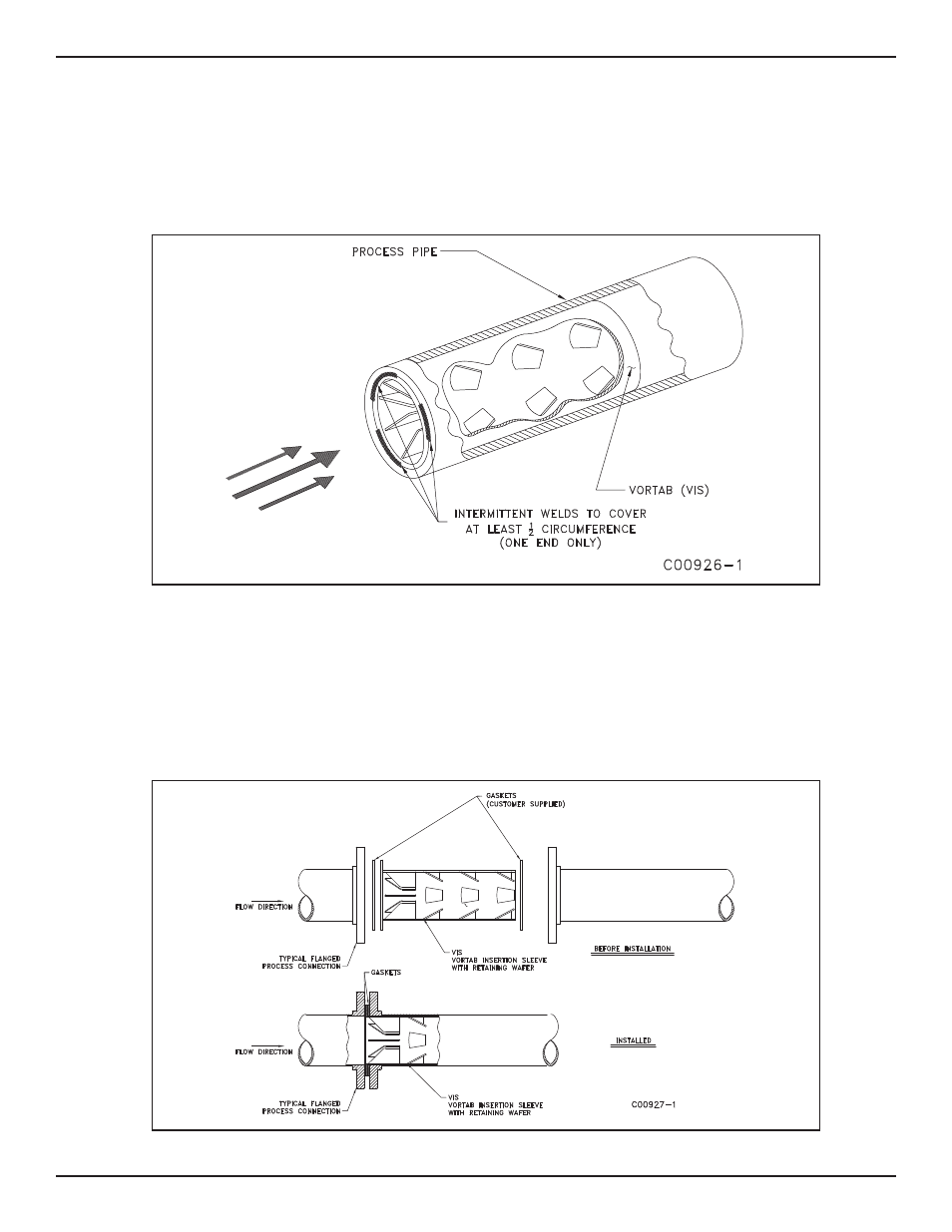
Tack Weld Mounting
Slide the VIS into the process pipe. Orientation of the tabs is not critical although symmetry with the downstream flow metering device is recom-
mended. Weld Vortab into place; at least 1/2 of circumference should be securely welded. See Figure 2-8.
Note:
Depending on size, there may be an additional sizing ring enclosed in the shipping container. This is used for fabricating and
inspection purposes and can be discarded upon completion of installation.
If the VIS does not fit, use the sizing ring to determine where the flow conditioner is out-of-round. Carefully reshape the problem area and reinstall
the VIS.
Figure 2-8. Typical Welded Installation of a VIS
Retaining Wafer Mounting
Sandwiching the retaining wafer between flange faces secures the VIS in place. This will require two customer-supplied gaskets of which one will
be placed on each side of the retaining wafer prior to installation. Orientation of the tabs is not critical although symmetry with the downstream flow
metering device is recommended. Bolt flanges together to complete installation. See Figure 2-9.
Note:
Depending on size, there may be an additional sizing ring enclosed in the shipping container. This is used for fabricating and
inspection purposes and can be discarded upon completion of installation.
Figure 2-9. Typical Retaining Wafer Mounting of a VIS