Fluid Components International VORTAB User Manual
Page 4
VORTAB
®
Company
VORTAB Flow Conditioner
This page is subject to the proprietary rights statement on the last page
4
Doc. No. 06EN003269 Rev. D
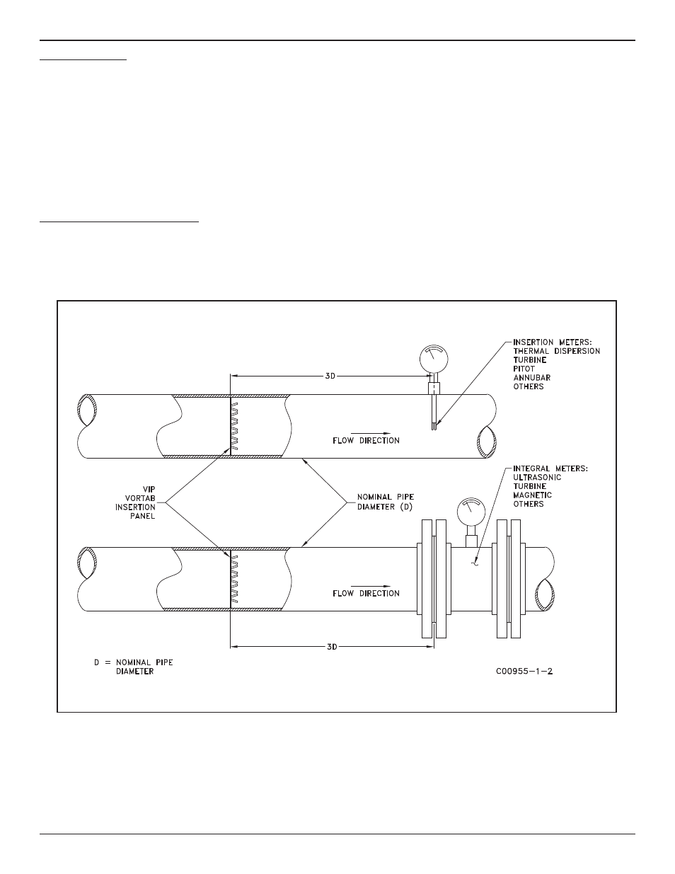
Figure 2-1. VIP Installation Recommendations
Installation - General
Receiving and Inspection
• Inspect for damage
• Packing List – verify correct configuration against purchase order. At a minimum, Vortab Company’s customer order number along with flow direc-
tion indicators will be etched on all products.
• If the above items are satisfactory then proceed with installation. If not, then STOP and contact the field representative or the factory personnel
for instructions.
There may be an additional sizing ring accompanying the Vortab Insertion Sleeve (VIS) in the shipping container. This is used to verify roundness and
diameter during fabrication. It may be needed to facilitate installation in the following sections. The sizing ring can be discarded upon completion of
the VIS installation.
Vortab Insertion Panel (VIP) Installation
Prepare the installation site or inspect the already prepared location to assure that the VIP will fit into the process pipe or duct.
• Verify that the VIP matches the geometry and dimensions of the intended process pipe mount.
• The VIP’s base plate, in which the tabs extend from, should be positioned at a distance of three nominal pipe diameters (3D) upstream from the
flow meter location. See Figure 2-1.