Fluid Components International VORTAB User Manual
Page 7
VORTAB Flow Conditioner
VORTAB
®
Company
Doc. No. 06EN003269 Rev. D
7
This page is subject to the proprietary rights statement on the last page
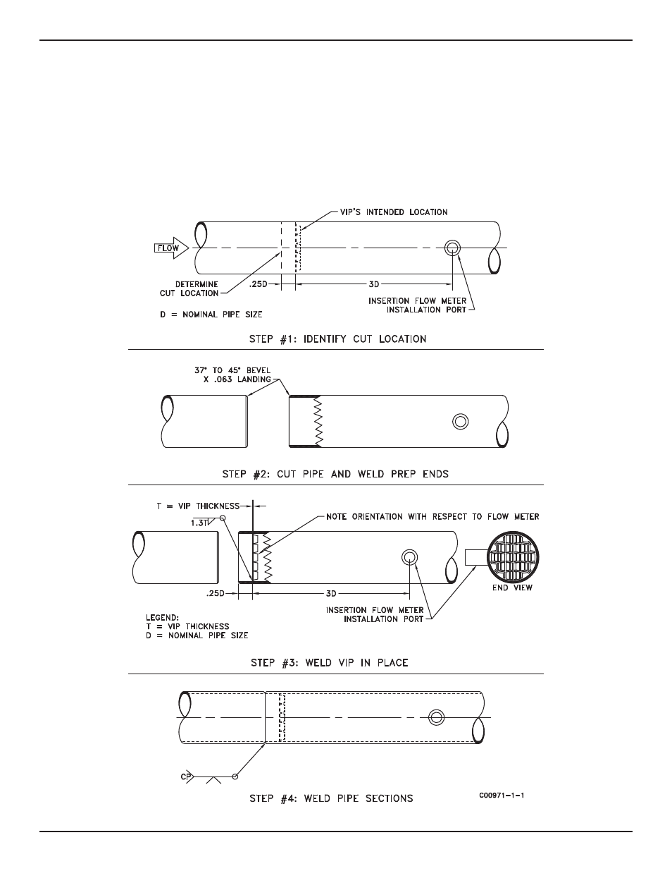
Refer to Figure 2-6 for installation recommendations. Welding the VIP into place may cause distortion and shrinkage to the receiving conduit’s wall
so it is suggested to weld the VIP away from any potential weld zones like that shown Step #1 of Figure 2-6. First identify the permanent location
of the VIP and determine the receiving conduit’s cut location (if required). It is recommended to position the VIP a quarter of a pipe diameter (.25D)
downstream from conduit re-weld zone. Before any welding is to take place, weld prep pipe ends if required per step #2. Position and correctly
orientate the VIP .25D downstream from conduit weld zone and provide full circumferential fillet weld to secure VIP in place per step #3. Complete
installation by welding conduit sections back together per step #4. Avoid welding the VIP flush with flange faces as warping or shrinkage of the
flange face may occur.
When using the VIP upstream from flow meters other than FCI insert flow meters, whether it be in insert or flange mounted, such as turbine, annubar,
and ultrasonic flow meters, orientation is not critical but should mimic that which was calibrated. The VIP should be positioned upstream from the
flow meter in the orientation and distance in which it was calibrated.
Figure 2-6. Weld-In-Place VIP Installation