Wiring the version with both relay and current, Outputs (5-pin m12 fixed connector) – Burkert Type 8072 User Manual
Page 25
23
Installationandwiring
+ -
i
(*)
+ -
4
3
1
2
5
i
i
Power supply
12-36 V DC
4-20mA input
(at external
instrument)
brown
blue
shield
black
white
grey
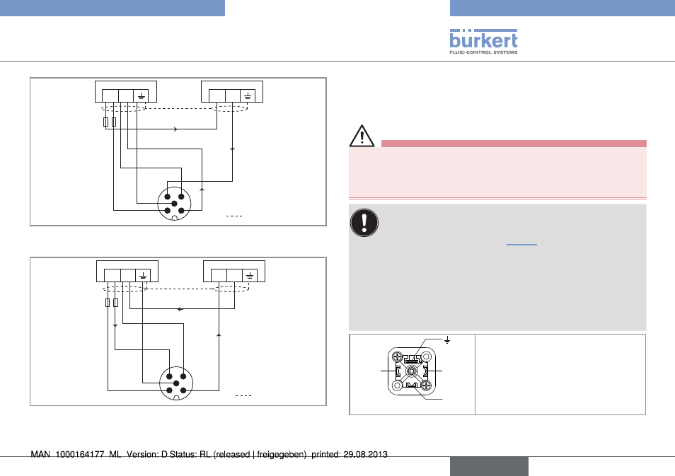
Fig. 24: Wiring of the current output, in sinking mode, of a
version with a single 5-pin M12 fixed connector
+ -
i
(*)
+ -
4
3
1
2
5
i
i
shield
grey
Power supply
12-36 V DC
4-20mA input
(at external
instrument)
brown
blue
black
white
Fig. 25: Wiring of the current output, in sourcing mode, of a
version with a single 5-pin M12 fixed connector
(*) Functional earth
7.3.6. Wiring the version with both relay
and current outputs (5-pin m12 fixed
connector)
Warning
shock hazard due to the voltage at the relay terminals, which
is higher than 48v.
• Before powering the device, always check that the connectors
are correctly plugged-in and tightened.
the device is not tight when the en 175301-803 fixed
connector is not wired:
→
Unscrew the nut [1] (see Fig. 10) on the 2508 female
connector supplied with the device.
→
Insert the plug with order code 444509, supplied with
the device, into the cable gland.
→
Screw the nut back.
→
Plug the sealed 2508 connector onto the
EN 175301-803 fixed connector.
1
2
3
1
2
3
1: Common
2: Relay, normally closed (NC)
3: Relay, normally open (NO)
4: not connected
Fig. 26: Pin assignment on the EN 175301-803 fixed connector
English
installation and wiring