Installation onto the pipe, Diagrams, English – Burkert Type 8072 User Manual
Page 17
15
Installationandwiring
l/min
l/s
DN 50 (DN65)*
DN 40 (DN50)*
DN 32 (DN40)*
DN 25 (DN32)*
DN 20 (DN25)*
DN 15 (DN15 / DN20)*
5000
1000
100
3
2
1
20
10
0.5
5
0.3
0.2
500
100
50
10
0.1
0.05
0.01
0.005
5
1
50
0.5
0.01
0.02
0.05
0.1
0.2
0.5
1
2
5
10
20
50
100
200
m
3
/h
0.1
0.3 0.5
1
2 3 5
10
0.2
m/s
DN 08
DN 06
Flow velocity
Flow rate
Warning
risk of injury due to nonconforming installation.
• The electrical and fluid installation can only be carried out by
qualified and skilled staff with the appropriate tools.
• Install appropriate safety devices (correctly rated fuse and/or
circuit-breaker).
• Respect the assembly instructions for the fitting used.
risk of injury due to unintentional switch on of power supply
or uncontrolled restarting of the installation.
• Take appropriate measures to avoid unintentional activation of
the installation.
• Guarantee a set or controlled restarting of the process subse-
quent to any intervention on the device.
To ensure that the device runs correctly, plug in and tighten
the connectors.
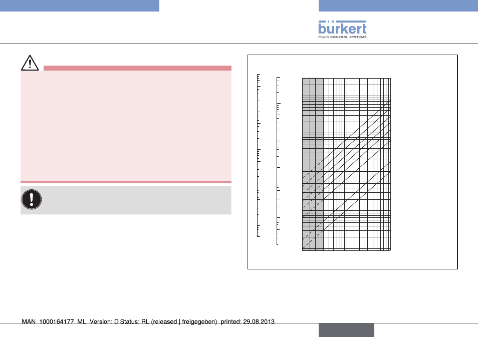
7.2.
installation onto the pipe
7.2.1. Diagrams
These diagrams are used to determine the DN of the fitting (only
for a threshold detector / flowmeter 8032) appropriate to the appli-
cation, according to the fluid velocity and the flow rate.
English
installation and wiring