Connection modules, Structure of the connection module – Burkert Type 8644 User Manual
Page 30
30
Structure and function of the modules
7.2.
connection modules
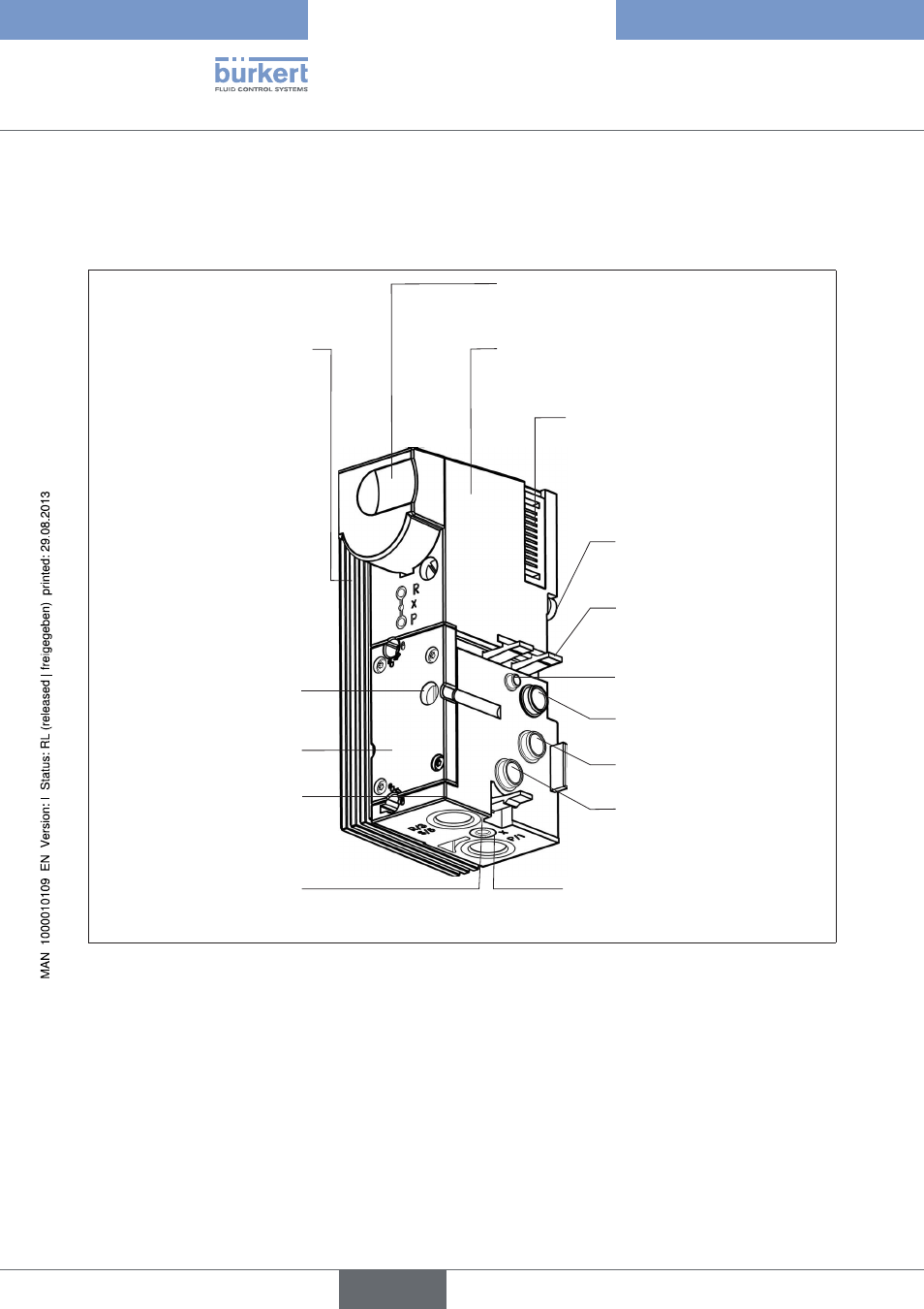
structure of the connection module
7.2.1.
Pneumatic feed
Type MP11/MP12 (left, middle, right)
Electrical connection module
Type ME02/ME03 (left, right)
Interface to electrical part of
the automation system (field
bus nodes; electrical modules/
terminals)
Shunting
(socket on left, plug on right)
Electrical interface for data shunting
within the Bürkert AirLINE system
Type 8644
Panel
Assembly variant with pressure gauge
Cover plate
Catch hook - Mechanical
attachment for pneumatic base
modules MP11/MP12
X - Pilot control exhaust air
connection
(R) 3
Exhaust air connection
(S) 5
Exhaust air connection
(P) 1
Pressure supply connection
Screws
Fastening screws for rail
assembly
Clamps
Fastening clamps for rail
assembly
(P) 1
Pressure supply connection
X - Pilot control exhaust
air connection, control
assist air connection
(R) 3 + (S) 5
Structure of the connection module
Figure 9:
Variants
The feeds were designed in different variants to meet diverse requirements. To facilitate start-up and diagnosis, feeds
are available with a pressure gauge. You receive the fluid connections with straight or conical screw connections
as well as with quick-connect systems.
The fluid connections can be used differently for special functions. For example the vent connection for the pilot
valve can be used as a connection for the control assist air, and different pressures can be applied for supplying
and controlling the valve.
Typ 8644
deutsch