Burkert Type 8691 User Manual
Page 19
19
Electrical installation
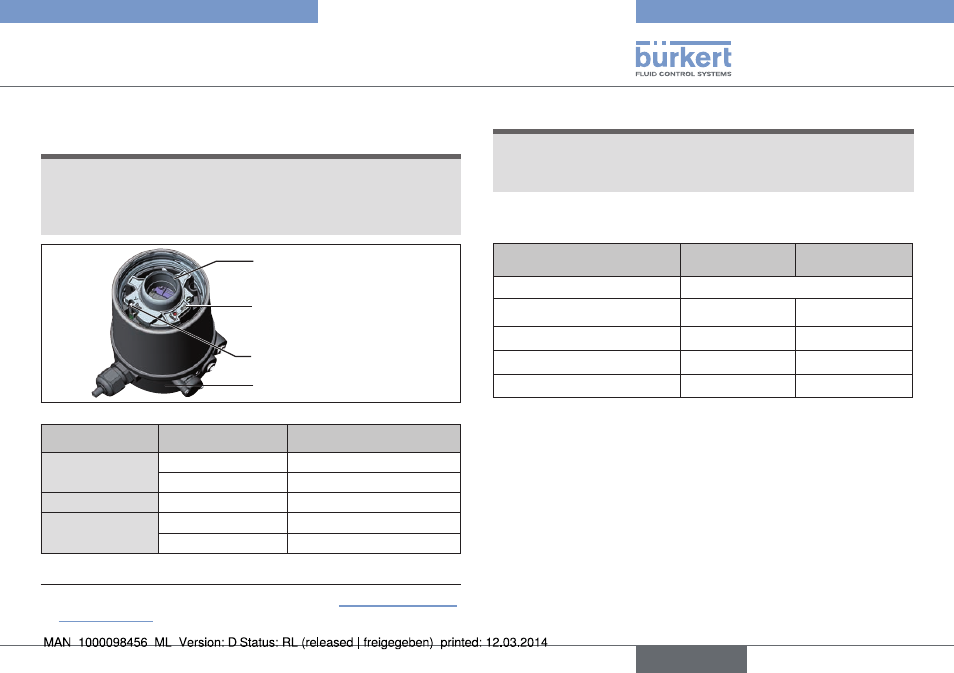
9.3 Display elements 24 V Dc
note!
Breakage of the pneumatic connection pieces due to rota-
tional impact.
▶ When unscrewing and screwing in the transparent cap, do not
hold the actuator of the process valve but the connection housing.
LED pilot valve (yellow)
Status LED (yellow)
Top LEDs
Connection housing
Fig. 14: Display elements 24 V DC
led
color
top leds
3)
is lit green
End postion bottom
is lit yellow
End postion top
led pilot valve
is lit yellow
Pilot valve is actuated
status led
flashing yellow
Teach function is running
flickers yellow
Puck PCB not available
Tab. 3: Display elements 24 V DC
3)
Color setting ex works. Can be set via jumper (see “Fig. 11: Connection
with cable gland”).
note!
damage or malfunction due to penetration of dirt and humidity.
▶ To observe degree of protection IP65 / IP67, screw the trans-
parent cap in all the way.
9.4 programming data aS-interface
as-interface
31 slaves
as-interface
62 slaves
I/O configuration
B hex (1 input, 2 outputs)
ID code
F hex
A hex
Extended ID code 1
F hex
7 hex
Extended ID code 2
F hex
E hex
Profile
S-B.F.F
S-B.A.E
Tab. 4: Programming data
english
Type 8691