2 electrical installation 24 v dc – Burkert Type 8691 User Manual
Page 17
17
Electrical installation
9.2 electrical installation 24 V Dc
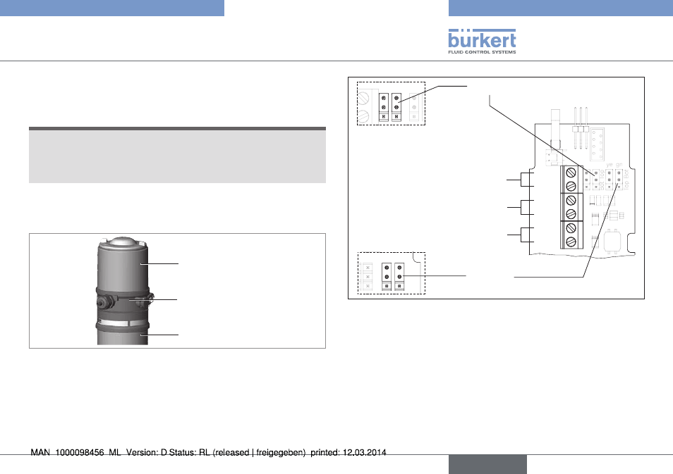
9.2.1 electrical installation with cable gland
note!
Breakage of the pneumatic connection pieces due to rota-
tional impact.
▶ When unscrewing and screwing in the body casing, do not hold
the actuator of the process valve but the connection housing.
→
Unscrew the body casing (stainless steel) in a counter-clockwise
direction.
Body casing
Connection housing
Actuator
Fig. 10: Open control head
→
Push the cables through the cable gland.
→
Connect the wires.
IN 1
IN 2
24 V
Valve
+
-
+
-
Jumper:
Color assignment of the Top LEDs
Screw terminals
end positions
Screw terminals
Supply 24 V DC
Screw terminals
Valve (control)
ye gn
To
p
Bot
Bot
To
p
IN 1 = Top (top)
IN 2 = Bot (bottom)
ye gn
To
p
Bot
Bot
To
p
Jumper: assignment p-n-p or n-p-n
outlet (optional)
Fig. 11: Connection with cable gland
english
Type 8691
- Type 0125 (15 pages)
- Type 0121 (4 pages)
- Type 6012 (4 pages)
- Type 0330 (2 pages)
- Type 0331 (4 pages)
- Type 0127 (18 pages)
- Type 0131 (5 pages)
- Type 0141 (5 pages)
- Type 0142 (12 pages)
- Type 0145 (3 pages)
- Type 0174 (5 pages)
- Type 0212 (2 pages)
- Type 0211 (5 pages)
- Type 0212-B (18 pages)
- Type 0250 (64 pages)
- Type 0253 (2 pages)
- Type 0255 (15 pages)
- Type 0355 (2 pages)
- Type 0255 (2 pages)
- Type 8640 (55 pages)
- Type 8640 (119 pages)
- Type 8006 (34 pages)
- Type 8640 (2 pages)
- Type 0256 (15 pages)
- Type 0256 (2 pages)
- Type 0258 (72 pages)
- Type 0262 (5 pages)
- Type 0273 (6 pages)
- Type 0280 (12 pages)
- Type 0280 (5 pages)
- Type 0280 (2 pages)
- Type 0281 (2 pages)
- Type 0282 (2 pages)
- Type 0283 (2 pages)
- Type 0286 (4 pages)
- Type 0287 (15 pages)
- Type 0290 (14 pages)
- Type 0290 (2 pages)
- Type 0293 (18 pages)
- Type 0300 (6 pages)
- Type 0301 (6 pages)
- Type 0311 (2 pages)
- Type 0312 (6 pages)
- Type 6519 (4 pages)
- Type 6519 (2 pages)