Burkert Type 0333 User Manual
Page 4
8
5.6 electrical data
Connections
DIN EN 175301-803 (DIN 43 650), shape A for
cable plug Type 2508 or 2509
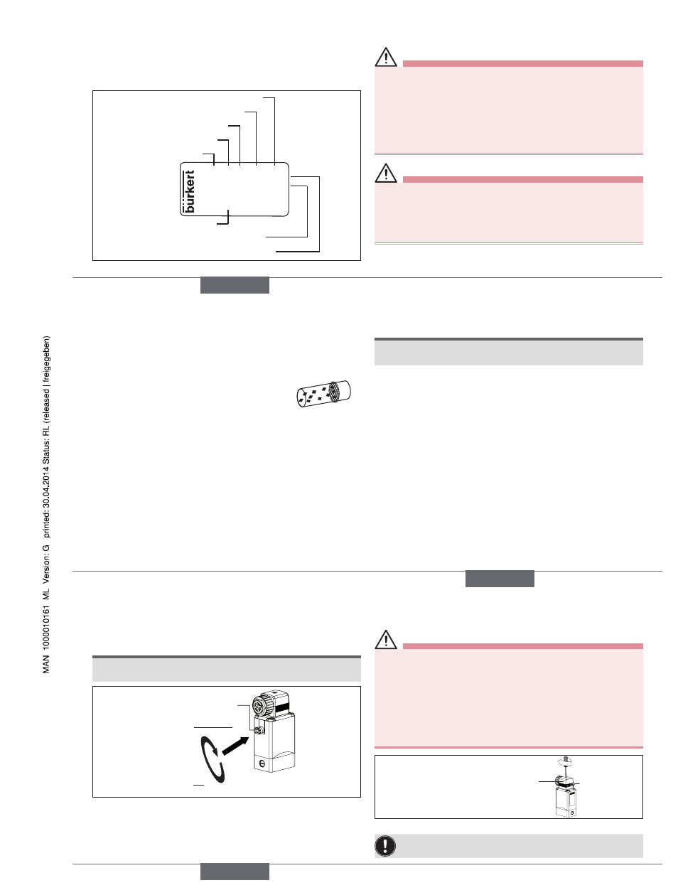
5.7 Type label
Made in Germany
00450000
W14UN
CE
0330 C 2.0 FKM MS
G1/4 0-6 bar
24V DC 8W
Identification number
Voltage, frequency, output
Port connection, nominal pressure
Type
Circuit function
Orifice
Sealing material
Body material
Fig. 1:
Description of the type label (example)
6
assemBly
Danger!
Risk of injury from high pressure in the system/device.
▶ Before working on the system or device, switch off the pressure
and vent/drain lines.
Risk of injury due to electrical shock.
▶ Before working on the system or device, switch off the power sup-
ply and secure to prevent reactivation.
▶ Observe applicable accident prevention and safety regulations for
electrical equipment.
WarnIng!
Risk of injury from improper assembly.
▶ The assembly may be carried out only by trained technicians and
with the appropriate tools.
▶ Secure system against unintentional activation.
▶ Following assembly, ensure a controlled restart.
english
9
6.1 Before installation
Installation position:
The installation position is optional. Preferably: Actuator at the top.
→
Prior to installation check pipelines for dirt and clean if necessary.
Dirt filter: To ensure that the solenoid valve func-
tions reliably, a dirt filter (
≤ 500 µm) must be
installed in front of the valve input.
6.2 installation
→
Observe flow direction:
Functioning of the device is only ensured if the circuit function is
maintained.
Devices in socket model
→
Use PTFE tape as sealing material.
→
Determine the maximum screw-in depth of the connecting threads
as this does not comply with any standard.
note!
Caution risk of breakage.
▶ Do not use the coil as a lifting arm.
→
Hold the device with a suitable tool (open-end wrench) on the
body; screw into the pipeline.
Attaching the device:
→
Via bore holes M4x8 (made from brass or stainless steel) or self-
tapping screws 3.9 DIN 7970 (made from plastic, max. screw-in
depth 10 mm) on the bottom side of the body at drill pattern
38x24.
Devices in flange model
Attaching the device:
→
Via supplied screws on basic devices or manifold.
→
Tighten fastening screws on the coil to a maximum torque of 2 Nm.
english
10
6.3 manual control
note!
▶ When the manual control is locked, the valve cannot be actuated
electrically.
1
2
Press
Turn
Manual control
Fig. 2:
Manual control
7
elecTrical connecTion
Danger!
Risk of injury due to electrical shock.
▶ Before working on the system or device, switch off the power sup-
ply and secure to prevent reactivation.
▶ Observe applicable accident prevention and safety regulations for
electrical equipment.
If the protective conductor is not connected, there is a risk of
electric shock.
▶ Always connect protective conductor and check electrical continuity
between coil and housing.
Approved cable plug, e.g. Type
2508 or other suitable cable plug
in accordance with
DIN EN 175301-803 shape A
max. 1 Nm
Seal
Fig. 3:
Connecting the cable plug to the power supply
Note the voltage and current type as specified on the type label.
english
Type 0121 / 0330 / 0331