Brooks, Model 5851 i – Brooks Instrument 5851i User Manual
Page 36
4-8
Installation and Operation Manual
X-TMF-5851i-MFC-eng
Part Number: 541B109AAG
September, 2009
Brooks
®
Model 5851
i
Section 4 Maintenance
& Troubleshooting
6. Remove and note the position of the valve spring spacers (10) which
may be located above and/or below the lower valve springs (8).
7. Unscrew the orifice (12) from the flow controller body (14) using the
orifice removal tool. (See Section 5, Table 5-2.)
8. Remove the three screws (20) attaching the electronics cover. Remove
the upper jack post on the D-connector. Remove the electronics cover
(23).
9. Unplug the sensor connector from the PC Board. Remove the two
screws (20) securing the bracket (24) and PC Board (15). Remove the
bracket and PC Board.
10. Remove the two hex head screws (18) using a 1/8" hex wrench, and
washers (19) securing the sensor assembly (16). Remove the sensor
assembly.
NOTE: Do not attempt to disassemble the sensor assembly.
11. Remove the sensor assembly O-rings (17) from the flow controller
body (14). Using the Brooks O-ring removal tool will help prevent
scratching the sealing surface.
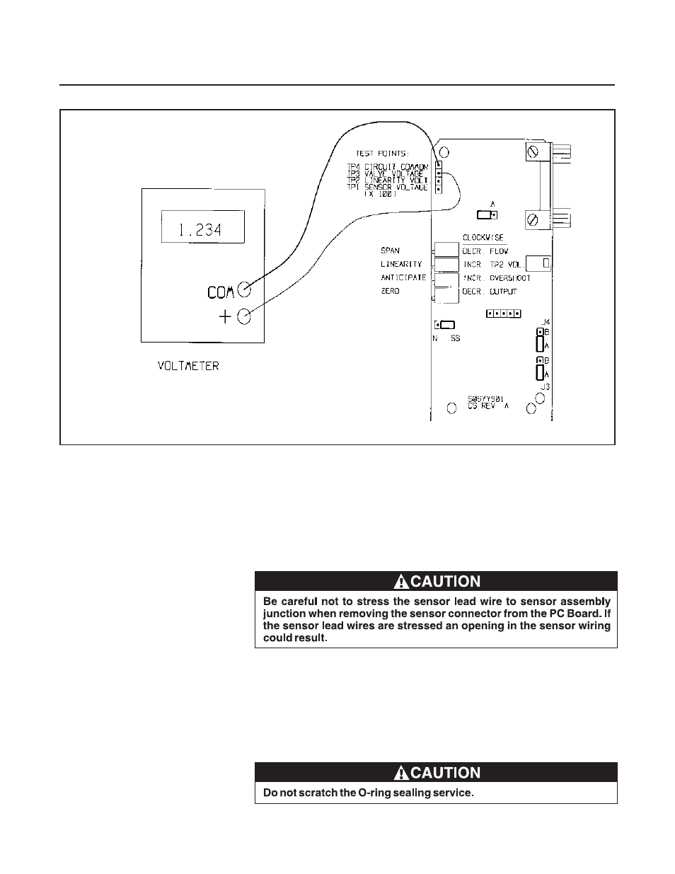
Figure 4-3 Voltmeter Connections for Valve Adjustment