Brooks, Model 5851 i – Brooks Instrument 5851i User Manual
Page 27
3-9
Installation and Operation Manual
X-TMF-5851i-MFC-eng
Part Number: 541B109AAG
September, 2009
Brooks
®
Model 5851
i
Section 3 Operation
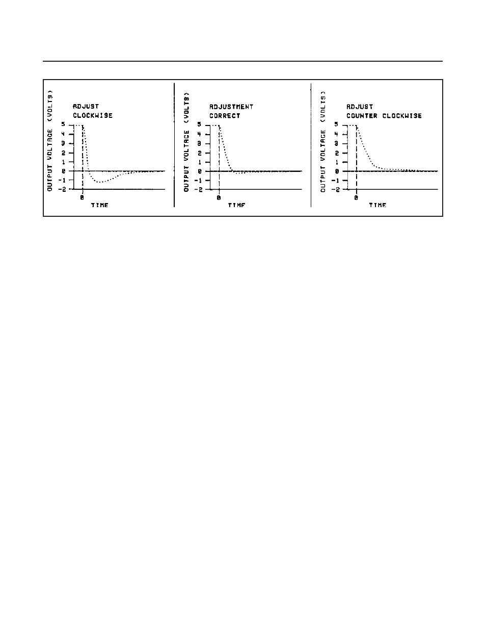
Figure 3-6 Fast Response Adjustment
a. Set the command potentiometer for 100% flow (5.00V) and wait
about 45 seconds for the flow output signal to stabilize.
b. Step the command signal to 0% or activate valve override closed to
stop the flow. Observe the flow signal output as it decays.
c. The behavior of the flow signal during this transition between 100%
and 0% flow indicates the adjustment required of the anticipate
potentiometer. Refer to Figure 3-6.
d. If the flow signal measured on pin 2 decays to -0.05 to -0.5V, then
rises to 0V, the anticipate potentiometer is properly adjusted.
e. If the flow signal decays rapidly and goes below -0.5V before rising to
0 V, the anticipate potentiometer must be adjusted clockwise and
steps a and b repeated.
f. If the flow signal decays slowly and does not go below -0.05 V, the
anticipate potentiometer must be adjusted counterclockwise and
steps a and b repeated.
2. Fast response adjustment (six second response specification
guaranteed)
Adjustment of the anticipate potentiometer to obtain a flow rate
performance to be within 2% of flow rate commanded in less than six
seconds after setpoint change requires the use of a fast response
flowmeter (500 millisecond response to be within 0.2% of final value or
better) in series with the 5851i and a storage oscilloscope or recorder.
a. Allow the flow controller to stabilize at 0% setpoint for at least thirty
seconds. Make a step in setpoint to the controller from 0-100% of
full scale flow and record the output signal of the fast response
flowmeter.
b. If this signal shows more than 4% overshoot, adjust the anticipate
potentiometer one-half to one turn counterclockwise. If the signal
does not show overshoot but is not within 2% full scale of final value
after six seconds, adjust the anticipate potentiometer one-half to one
turn clockwise. Set command potentiometer for 0% of flow.
c. Repeat steps a and b until the fast response flowmeter output signal
meets the specified response requirements.
NOTE: With the above equipment, the anticipate potentiometer can be
adjusted to give optimum response characteristics for any process.