Brooks, Model 5851 i – Brooks Instrument 5851i User Manual
Page 24
3-6
Installation and Operation Manual
X-TMF-5851i-MFC-eng
Part Number: 541B109AAG
September, 2009
Brooks
®
Model 5851
i
Section 3 Operation
j. Set the command potentiometer for 100% flow (5.000V). Connect the
DVM positive lead to TP2 and the negative lead to TP4.
k. Adjust the linearity potentiometer for an output equal to the new
calculated TP2 voltage.
l. Repeat steps f, g and h.
1. If the error recorded in step “h” is less than 0.5%, then the calibration
procedure is complete.
2. If the error is greater than 0.5% set the command potentiometer for
100% (5.000V). Connect the DVM positive lead to TP2 (linearity
voltage) and the negative lead to TP4 (circuit common).
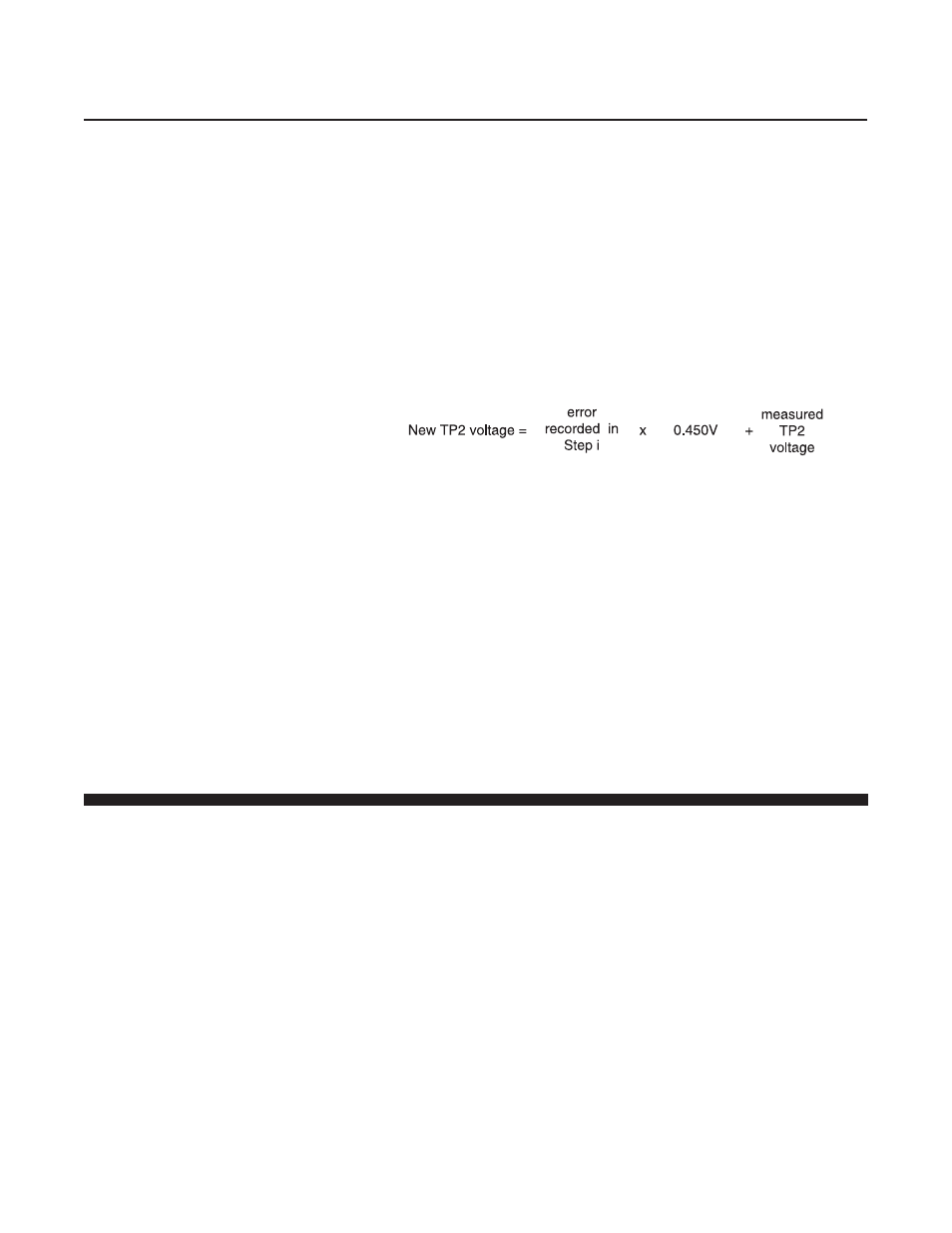
Calculate a new TP2 voltage as follows:
Example:
Controller error = 0.7%
Measured TP2 voltage = -0.567 volts
TP2 correction = 0.7 x 0.450 = 0.315 volts
New TP2 correction = 0.315 + (-0.567) = -0.252 volts
Adjust the linearity potentiometer for an output equal to the new TP2
voltage and then repeat steps f, g and h.
NOTE: The voltage at TP2 can range from -10 to +3 volts, however, it is
recommended that this voltage stays between -2.5 and +2.5 volts for
proper operation. If the recommended voltage range is exceeded, the
desired accuracy and/or signal stability may not be achieved. If one of the
limits is reached, check the restrictor sizing. Refer to Section 4-7.
3-5 Response
Fast Response Adjustment
Two methods of adjusting the step response of the 5851i mass flow
controllers can be used.
Method Number 1 describes a procedure that will get the step response
close to optimum quickly and without any flow measuring equipment.
This method should be used when the response time of the flow
controller is not critical to overall system performance.
Method Number 2 describes a procedure that will allow adjustment of your
5851i mass flow controller to optimum step response performance.
This method is the preferred way to adjust the step response.
Adjustment of the fast response circuit will not affect the accuracy of
the flow controller as adjusted in Section 3-4.
1. Fast response adjustment (six seconds response specification not
guaranteed)
NOTE: This procedure requires an oscilloscope, chart recorder or a DVM
with a sample speed of three samples per second or greater to monitor the
rate of change of the output signal.