Communication Concepts AN758 User Manual
Page 8
AR
C
HIVE INF
O
RMA
TI
O
N
PRODUCT TRANSFERRED T
O
M/A
–
COM
AN758
8
RF Application Reports
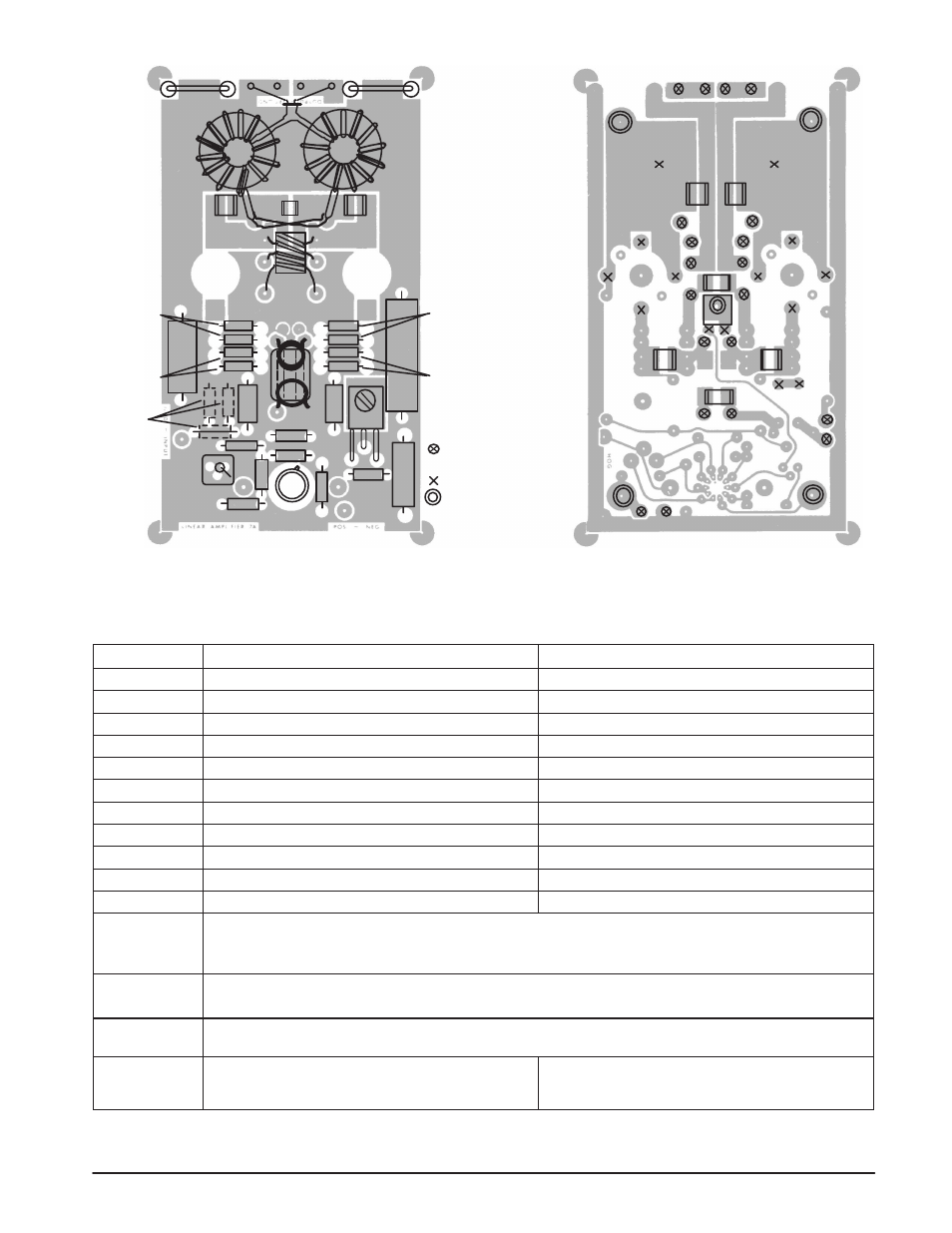
Optional
Input
Atten-
uator
Q1
Q2
R4
R2
R3
R1
L4
L3
T3
C7
C6
C8
C
C
T2
E
E
E
E
B
C11
C13
Q3
L2
L1
T1
R5
C12
R6
R10
R9
R8
R12 D2
R7
MC1723C
D1
C1
C2
C3
A.
B.
Terminal Pins and
Feedthroughs
Feedthrough Eyelets.
Stand Off’s
Figure 9. Component Layout of the 300 W Amplifier Module
PARTS LIST*
(Power Module and Driver Amplifier)
Power Module
Driver Amplifier
C1, C2
5600 pF
3300 pF
C3
56 pF
39 pF
C4
470 pF
Not Used
C5
560 pF
470 pF
C6
75 pF
51 pF
C7, C8
0.1
µF
0.1
µF
C9, C10
0.33
µF
0.33
µF
C11
10
µF/150 V
10
µF/150 V
R1, R2
2 x 3.9
Ω / 1/2 W in parallel
2 x 7.5
Ω / 1/2 W in parallel
R3, R4
2 x 6.8
Ω / 1/2 W in parallel
2 x 18
Ω / 1/2 W in parallel
L1, L2
Ferroxcube VK200 19/4B ferrite choke
Ferroxcube VK200 19/4B ferrite choke
L3, L4
6 ferrite beads each, Ferroxcube 56 590 65/3B
6 ferrite beads each, Ferroxcube 56 590 65/3B
All capacitors, except C11, are ceramic chips. Values over 100 pF are Union Carbide type 1225 or 1813 or Varadyne
size 18 or 14. Others ATC Type B.
T1
9:1 type, see text.
4:1 type, see text.
(Ferrite core for both: Stackpole 57-1845-24B or Fair-Rite Products 287300201 or equivalent.)
T2
7 turns of bifilar or loosely twisted wires. (AWG #20.)
Ferrite cores for both: Stackpole 5-9322, Indiana General F627-8Q1 or equivalent.
T3
14 turns of Microdot 260-4118-00 25
Ω miniature coaxial
cable wound on each toroid. (Stackpole 57-9074, Indiana
General F624-19Q1 or equivalent.)
11 turns of RG-196, 50
Ω miniature coaxial cable wound
on a bobbin of a Ferroxcube 2616P-A100-4C4 pot core.
* Parts and kits for this amplifier are available from Communication Concepts Inc., 508 Millstone Drive, Beavercreek, Ohio 45434–5840
(513) 426-8600.