Communication Concepts AN758 User Manual
Page 11
AR
C
HIVE INF
O
RMA
TI
O
N
PRODUCT TRANSFERRED T
O
M/A
–
COM
AN758
11
RF Application Reports
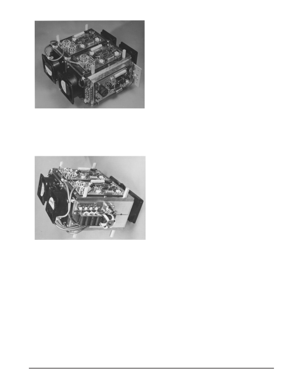
Figure 14. 1 kW Linear Amplifier showing the input
power divider in the foreground, to the right is the
preamplifier. Two of the four 300 W modules can be
seen on the upper side of the structure. The other two
modules are shown in Figure 15.
Figure 15. 1 kW Linear Amplifier showing the output
combiner in the foreground, to the right is the 1:4
stepup transformer. The four balancing resistors,
mounted to the heat sink, can be seen directly above
the combining network.
From the BH curves we can see that the linear portion
extends to 800 – 1000 gauss, and the saturation occurs at
over 3000 gauss. Comparable materials are Stackpole grade
14 and Fair-rite products 63.
The core losses are minimal compared to the line losses,
which for the 16
″ length amount to 0.035 dB or 0.81%.
As in the input transformer, the HF compensation (C2)
was not required. The lay-out of the combiner and T2 is such
that minimum lead lengths are obtained, and the structure
is mounted on a PC board having feedthrough eyelets to
a continuous ground plane on its lower side.
MEASUREMENTS
Six 300 W modules were built using matched pair
production MRF428’s. The maximum gain distribution was
0.9 dB, and in the four units selected for the amplifier, the
gain varied from 13.7 to 14.1 dB at 30 MHz, so it was not
necessary to utilize the option of the input attenuators.
Figure 16 shows the test set-up arrangement employed
for testing the modules and the combined amplifier.
The heatsink design was not optimized as it was felt to
be outside the scope of this report; concentration was made
in the electrical design. However, it was calculated to be
sufficient for short period testing under two-tone or CW
conditions at full power. The heatsink consists of four 9
″
lengths of Thermalloy 6151 extrusion, each having a free
air thermal resistance of 0.7
°C/W. They are bolted in pairs
to two 9
″ x 8 1/2″ x 3/8″ copper plates, to which the four
power modules are mounted. Assuming a coefficient of 0.85
between two parallel extrusions, a total thermal resistance
of 0.4
°C/W is realized. Two of these dual extrusions are
mounted back-to-back to provide a channel for the air flow
from four Rotron SP2A2 4
″ fans. Two are mounted in each
end of the heatsink, and the four fans operating in the same
direction provide an air flow of approximately 150 CFM.
The third order harmonic is 14 dB below the fundamental
at certain frequencies, as can be seen in Figure 22. This
number is typical in a four octave amplifier, and it is obvious
that some type of output filter is required when it is used
for communications purposes.
The 10:1 load mismatch was simulated with 34 feet of
RG-58 coaxial cable, which has an attenuation of
approximately 0.9 dB at 30 MHz, representing 1.8 dB return
loss. The coaxial was terminated into an LC network
consisting of a 2 x 15 — 125 pF variable capacitor and two
inductors as shown in Figure 23.
The high current mode appears at a phase angle of –90
°
and 20
Ω, where the monitored individual collector currents
increased to 6.8 A. At 50 V this amounts to 340 W, which
almost entirely represents device dissipation.
At 20:1 load mismatch an equal power dissipation is
reached at a power output of approximately 650 W CW.
Since the collector voltages remain below the device
breakdown at the high impedance mode (+90
°C,150 Ω), it
may be concluded, that the load mismatch susceptibility is
limited by overdissipation of the transistors.