Communication Concepts AN758 User Manual
Page 10
AR
C
HIVE INF
O
RMA
TI
O
N
PRODUCT TRANSFERRED T
O
M/A
–
COM
AN758
10
RF Application Reports
The main difference is at 2 MHz — and it was decided
that the 29 dB of isolation is sufficient, as the high frequency
isolation in either case is not much better. The 3E2A and
other similar materials are rather lossy at RF, and with their
low Curie points, would present a danger of overheating in
case of a source unbalance.
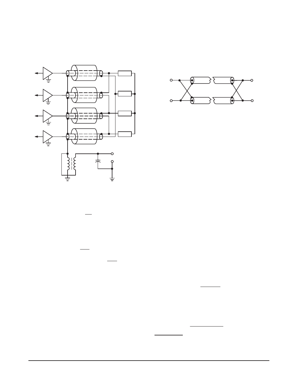
Figure 12 shows the electrical design of the four-port
power combiner.
C2
R
R
R
R
50 Ω
50 Ω
50 Ω
12.5 Ω
f
a
c
b
d
T2 = 1:4
50 Ω OUTPUT
50 Ω
Figure 12. Four Port Output Combiner
The power output with various numbers of disabled
sources, referring to Figures 11 and 12 can be calculated
as:
n
P
R
Pn – P
R
+
where:
n
= Number of Operative Sources.
Pn = Total Power of Operative Sources.
P
R
= Power Dissipated in Balancing Resistors.
For one disable source:
P
R
= 250
50
28.13
= 140.65 ,
Ǔ
ǒ
P
out
= (250 x 3) – 140.65 +
3
140.65
Ǔ
ǒ
= 750 – 187.5 = 562.5 W
This is assuming that the phase errors between the active
sources are negligible. Otherwise the formula in
(7)
can be
adapted, but if the errors between the active sources are
unequal, the situation will get rather complex.
From above we see that 140.65 W will be dissipated by
one of the balancing resistors and only 15.6 W by the other
three. For this high power dissipation the resistors must be
the type which can be mounted to a heat sink, and
noninductive. After experiments with the “noninductive”
wirewound resistors which exhibited excess inductance at
30 MHz and were bulky with 50 and 100 W ratings, thin film
terminations were specially fabricated in-house for this
application.* These terminations are deposited on a BeO
wafer, which is attached to a copper flange. They are rated
for 50 W continuous power, but can be operated at 100 or
even 150 W for nonextended periods if the flange
temperature is kept moderately low. The balancing resistors
can be seen on the upper side of the combiner, which is
shown in the foreground of Figure 15.
The purpose of the step-up transformer T2, (Figure 12)
is to transform the 12.5
Ω impedance from the combiner up
to 50
Ω. It is a standard 1:4 unbalanced-to-unbalanced
transmission line type transformer,
(6, 7, 8)
in which the line
is made of two RG-188 coaxial cables connected in parallel
in the manner as shown in Figure 13.
Figure 13.
Normally the loss in RG-188 at 30 MHz is 0.08 dB/foot.
In this connection arrangement, the currents in both
directions are carried by the braid in parallel with the inner
conductor and the power loss is reduced to approximately
0.025 dB/foot. The impedance becomes 25
Ω, and
depending on how close the cables are to each other
physically, it can be as low as 22
Ω. The minimum line
inductance can be calculated as shown before, and is 16
µH
for the 50
Ω side. This inductance is achieved by winding
several turns of the dual cable line on a magnetic core. In
contrast to the balun transformers in the combiner, the line
currents do not cancel and the magnetic core must handle
the full power, and must be made of lower loss material. The
form of a toroid was figured to require the shortest line length
for a specific inductance, and out of the standard sizes, two
stacked units resulted in a shorter line length than a single
larger one with similar cross sectional area.
Six turns on two Indiana General F626-12-Q1 toroids give
4.8 and 23
µH for the secondary; the line length being
16 inches.
In continuous operation the core temperature was
measured as 95 – 90
°C. This resulted in a decision to change
the core material to Q2, which exhibits about 70% lower
losses at 30 MHz. The permeability is also lower (35), and
with the same number of turns gives only 13
µH.
The line length could not be increased according to
(7)
,
and the measurements indicated no difference in operation
at 2 MHz, so the Q2 toroids with the low inductance were
considered permanent.
The maximum flux density of the toroids is calculated as
shown before:
2
πfηA
V
max
x 10
2
B
max
=
gauss ,
where:
V = Peak voltage across the secondary, (50 point)
316.2 V
f = Frequency in MHz (2.0)
η = Number of turns at the 50 Ω point. (12)
A = Core cross sectional area (1.21 cm
2
)
6.28 x 2 x 12 x 1.21
316.2 x 10
2
B
max
=
= 260 gauss
* Similar attenuators and terminations are available from Solitron,
EMC Technology, Inc., and other manufacturers of microwave com-
ponents.