CEMB USA C206 (A) User Manual
Page 5
I 0638
-
5
4
7
9
10
11
12
13
14
15
6
6
6
1
2
3
4
8
6
16
5
GB
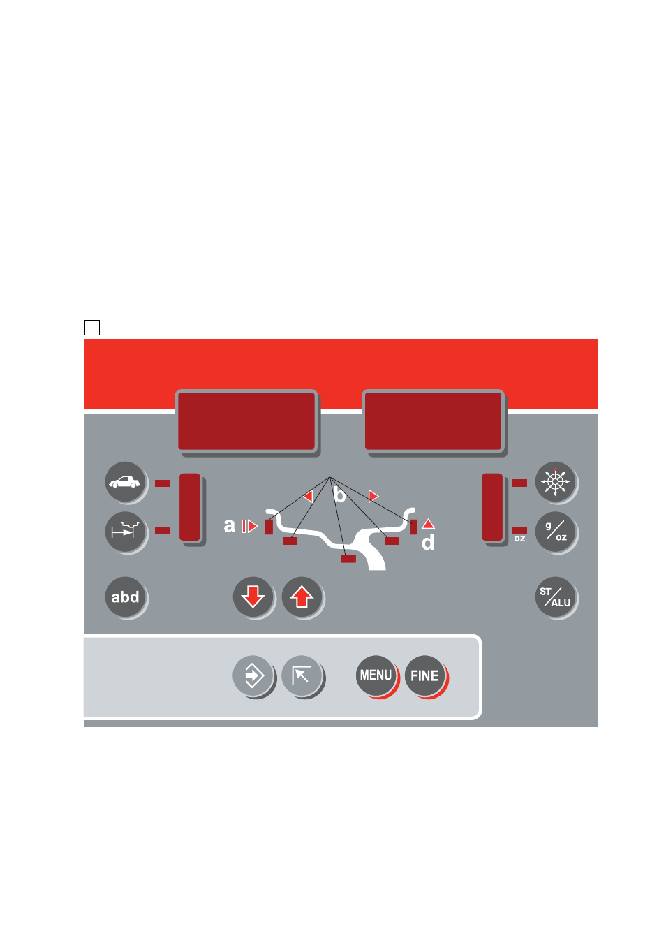
4 - CONTROLS AND COMPONENTS
4.1 - AUTOMATIC DISTANCE AND DIAMETER GAUGE
This gauge allows measurement of the distance of the wheel from the machine and the wheel diameter at the point
of application of the counterweight. It also allows correct positioning of the counterweights on the inside by using
the specifi c function (see
INDICATION OF EXACT CORRECTION WEIGHT POSITION
) which allows reading the position
used for the measurement within the rim.
4.2 - WHEEL LIFTING DEVICE
Allows lifting the wheel from the ground without using a lift in order to spin it.
It also allows lowering the wheel until it touches the ground in order to stop rotation
4.3 - MANUAL SPINNING DEVICE
Allows spinning the tyre until when the machine display turns off; this means that the minimum spindle rotation speed
has been reached to perform correct balancing (72’/min. for trucks and 100’/min. for cars). At this point, release the
handle and wait until the unbalance measured appears on the display.
4.4 - CONTROL PANEL AND DISPLAY
1-2
Digital readouts, AMOUNT OF UNBALANCE,
inside/outside
3-4
Digital readouts, POSITION OF
UNBALANCE,
inside/outside
5
Indicators, correction mode selected
6
Indicators, selection made
7
Push button, unbalance reading < 5 g (25 oz)
8
Push button, ounces/grams selection
9
Push button, selection of mode of correction
10
SPLIT push button (unbalance resolution)
11
Push button, FUNCTIONS MENU
12
Push button, menu selection confi rmation
13
Push button, car/truck selection
14
HOME Push button
15
Push buttons, manual dimensions setting
16 Position
repeat
N.B.: Only use the fi ngers to press the push buttons. Never use the counterweight pincers or other pointed objects.