Fiber optic panels, Fl2000 series fiber optic panel, Rack mount panel solutions – ADC Fiber Optic Panel FL2000 Series User Manual
Page 3
10/07
•
103743AE
Fiber
Optic
Panels
40
w w w . a d c . c o m
•
+ 1 - 9 5 2 - 9 3 8 - 8 0 8 0
•
1 - 8 0 0 - 3 6 6 - 3 8 9 1
Rack
Mount
Panel
Solutions
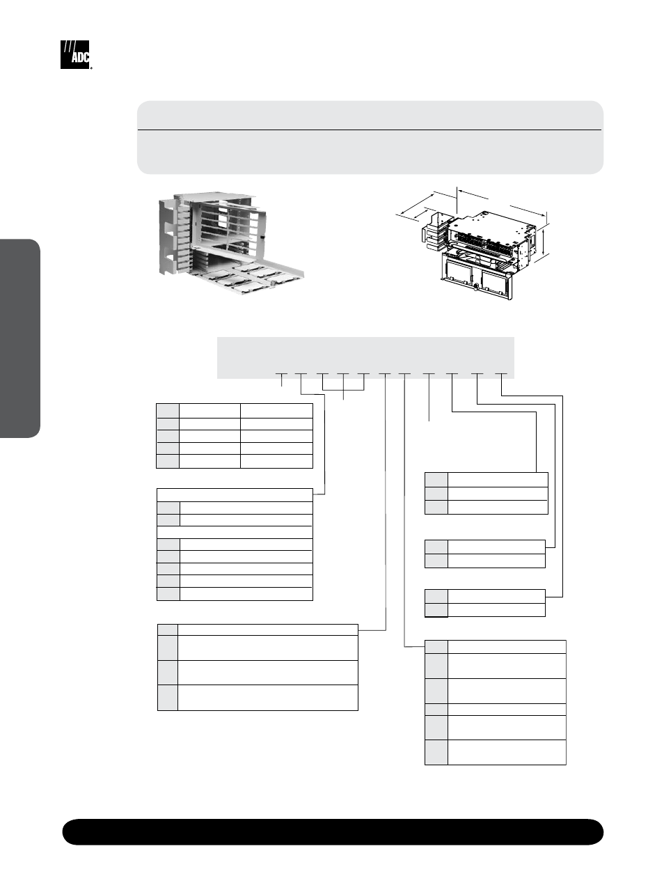
FL2000 Series Fiber Optic Panel
Fiber Termination/Splice Panel with Adapters or Pigtails
FL2 -
Catalog Number
0
-
Number
of Ports
Loaded
Number of
Splice Decks/Wheels
A
C
D
19" standard
19" flush mount
23" centered
Mounting Style
3
1
LC connectors and adapters double the capacity of the panel
by terminating two fibers at each adapter.
2
6-fiber softwall bundle except with LC connectors, which uses 12-fiber.
3
Mounting kit shipped unattached if other than standard mounting style.
1 clamp (standard)
2 clamps
0
2
Number of Cable Clamps
0
5
Latch
K1 lock
Latch Type
A
P
R
C
Adapter-only
Singlemode or multimode 62.5/125 µm
stranded softwall bundle
Singlemode or multimode 62.5/125 µm
12-fiber ribbon
Multimode 50/125 µm
stranded softwall bundle
Pigtail or Adapter Type
2
1
2
4
7
9
12-position 3.5" (2 RU)
24-position 5.25" (3 RU)
48-position 8.75" (5 RU)
72-position 14" (8 RU)
96-position 17.5" (10 RU)
Panel Capacity Panel Height
C
SC
LC
1
SC ultra polish
SC angled polish
FC ultra polish
LC
ultra polish
1
LC angled polish
1
Multimode
9
6
Singlemode
7
J
2
8
B
Connector and Adapter Type
0
M
W
1
2
3
None or N/A
Mechanical
(mass fusion)-wheel
Heat shrink fusion
(single fiber fusion)-wheel
Bare fusion
Heat shrink fusion
(single fiber fusion)-deck
Mechanical
(mass fusion)-deck
Splice Type
72-Position Termination/Splice Panel
(Shown Empty)
258 mm
(10.1")
126 mm
(5")
498 mm
(19.6")
133 mm
(5.25")
Other configurations are available upon request. Please contact ADC Technical Assistance Center.
Features
• Termination and splice panel
• Uses ADC’s splice deck or splice wheel
• VCG ships with each panel
• Uses FL2000 6paks with angled retainers
24-Position Termination/Splice Panel