Caution – C.E. Niehoff & Co. C627/C628/C631/C656/C657/C658/C671/C680 Troubleshooting Guides User Manual
Page 6
Page 6
TG30G
Section C: Comprehensive Troubleshooting
(CONT’D)
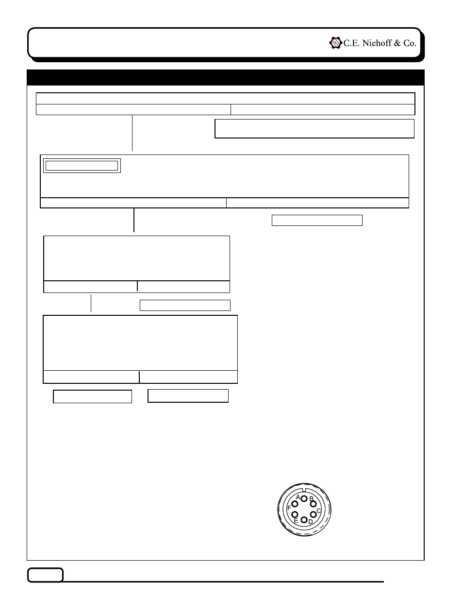
Figure 8 – Alternator-to-Regulator Harness Plug
PIN CONNECTIONS
Pin A
F–
Pin B
Phase
Pin C
B–
Pin D
B+
Pin E
D+
Pin F
F+
Chart 2 – No Output:
A2-155 Only
Alternator is defective.
Reconnect B+ battery cable to alternator. Turn on bat-
tery switch. Install a jumper from pin F in harness
plug to B+ terminal on alternator. Momentarily (1 sec.)
jumper pin A in harness plug to alternator B– terminal.
Touch shaft with steel tool to detect significant magne-
tism. Is shaft magnetized?
Yes
No
Alternator is defective.
Turn off battery switch and disconnect B+ battery
cable at alternator. Set DMM to diode test. Connect
black lead of DMM to pin E in harness plug. Connect
red lead to B+terminal on alternator. DMM should
read OL. Reverse leads. DMM should also read OL.
Yes
No
Alternator is defective.
Go to Chart 3, page 7.
With engine running, does battery voltage exist at alternator B+ terminal and regulator IGN terminal?
Yes
No
Repair vehicle harness circuit to IGN terminal on
regulator or B+ terminal on alternator.
With engine off: Unplug alternator-to-regulator harness. Connect DMM across pin D and pin C in harness
plug. Does battery voltage exist?
Yes
No
When conducting this step, ensure that the probes do not touch other pins, as an arc may damage
the wiring in the harness.
CAUTION