C.E. Niehoff & Co. A9-4039/A9-4050 Temperature-Voltage Sense Harness Instructions User Manual
Installation instructions, Notice
II182B
Page 1 of 1
A9-4039 Temperature-Voltage Sense Harness
and A9-4050 Temperature-Voltage/IGN/D+
Sense Harness
Installation Instructions
C. E. Niehoff & Co. • 2021 Lee Street • Evanston, IL 60202 Tech Services Hotline 800-643-4633
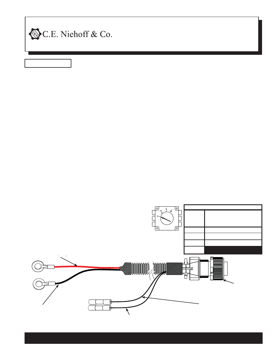
Table 1 – Regulator Select Switch Position
Switch
Position
Position 1
Position 2
Position 3
Position 4
Maintenance (D Category)
Maintenance-Free (Group 31)
AGM
DO NOT USE POSITION #4
Figure 1
A9-4039/A9-4050 Harness
Connected (Battery Type)
See NOTICE above
Figure 2 – A9-4039 and A9-4050 Temperature/Voltage Sense Harness Connections
Red wire — See step 3b
Black wire — See step 3b
DO NOT CUT UNLESS
ABSOLUTELY NECESSARY
See step 3a
A9-4039 and A9-4050 harness is optional equipment that can be used with many CEN 14 V or 28 V
regulators having the additional 5-pin round temperature/voltage sense connector. Contact CEN for regulator
selection.
• When A9-4039 or A9-4050 temperature/voltage sense harness is not connected, regulator will operate in
fi xed voltage setting determined by the select switch position on the bottom of the regulator. See separate
instructions with regulator.
• When A9-4039 or A9-4050 temperature/voltage sense harness is connected, regulator will automatically
optimize the charge voltage for battery type based on temperature. See column 2 in Table 1 and select switch
position based on battery type.
NOTICE
1. Remove hardware from regulator, turn regulator
over and select appropriate switch position
(See NOTICE above and Table 1 and Figure 1).
2. Reinstall regulator on alternator in the same posi-
tion as the previous regulator or in remote location
per vehicle manufacturer. Use screws and washers
(if supplied). On alternator, torque regulator mount-
ing screws to 8.5 Nm/75 lb. in.
3. Install temperature/voltage sense harness:
a. Remove cap from regulator and plug harness
connector into 5-pin connector.
b. Harness length varies, but long enough to reach
battery compartment in most vehicles. Unused
harness length should be coiled up. Use cable ties
every 12-14 inches to securely support harness
between regulator and battery compartment. If
harness length must be shortened:
1) Black wire—Do not shorten unless absolutely
necessary. If necessary, cut off first 6 inches
on terminal end and save cut piece to reat-
tach. Cut length off of remaining black wire.
Crimp and solder two ends and seal with
insulated butt splice.
2) Red wire—cut to desired length and use
terminal to connect.
3) Attach terminal from black wire in harness
to battery negative post and terminal from
red wire to 14V battery positive post for 14 V
systems or 28 V battery positive post for 28 V
systems.
c. A9-4050 harness has two additional wire connec-
tions for regulators requiring external ignition feed
or D+ voltage sense/reference signal. See Figure 2.
1) Green wire (D+)—Connect splice to vehicle volt-
age sense/signal wire. If terminal is used to run
relay, the relay coil must be diode protected and
rated for proper voltage. Crimp spliced end
securely. Use heat gun to seal splice. D+ termi-
nal provides 5 amps of 14 V or 28 V output.
2) Brown wire (IGN)—Connect splice to switched
voltage source from vehicle. Crimp end securely.
Use heat gun to seal splice.
4. Verify all electrical and mechanical connections to
regulator are tight.
A9-4050 ONLY: Green wire from
pin D (D+) — See step 3c
A9-4050 ONLY: Brown wire from
Pin A (IGN) —See step 3c