C.E. Niehoff & Co. A2-334/A2-335 Regulator Installation User Manual
Installation instructions
II179A
Page 1 of 1
A2-334 & A2-335
Regulators
Installation Instructions
C. E. Niehoff & Co. • 2021 Lee Street • Evanston, IL 60202 Tech Services Hotline 800-643-4633
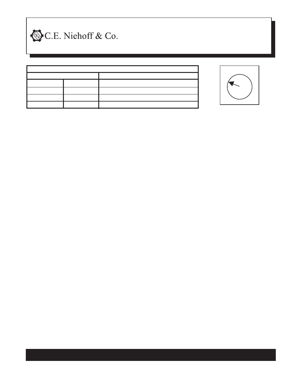
Table 1 – Voltage Select Switch Position
4 Voltage Setpoints (Fig. 1)
Position 1
14.0 V
Position 2
14.4 V
Position 3
14.8 V
Position 4
15.5 V
Battery Type
Maintenance (D Category)
Maintenance-Free (Group 31)
Maintenance-Free (Group 31)
Battery Isolator setpoint
Note: On Group 31 batteries, if boiling or excessive gassing occurs with high voltage
setpoint (position 3), change to medium voltage setpoint (position 2).
Figure 1 – 4 Voltage Setpoints
1. Before installing, turn regulator over and select
appropriate voltage setpoint for battery type
(See Table 1 and Fig. 1).
2. Install new regulator as described below:
• Mount A2-334 regulator on alternator in the
same position as the previous regulator. Use
screws and washers (if supplied). Torque
regulator mounting screws to 8.5 Nm/75 lb. in.
• Mount A2-335 regulator in remote location
specified by customer.
1
2 3
4
3. Plug the alternator-to-regulator harness into the
regulator.
4. Regulator connections:
• Connect IGN terminal to ignition source
through existing switch. Torque M5 terminal
nut on regulator to 4.5 Nm/40 lb. in.
• If required, connect P terminal to tachometer
or relay. P terminal taps AC voltage, typically
half the charge voltage. Torque M6 terminal
nut on regulator to 4.5 Nm/40 lb. in.