C.E. Niehoff & Co. 200 & 300: Regulator Upgrade Installation User Manual
Installation instructions
II0002C
Page 1 of 2
Series 200 & 300 Alternators
Installation Instructions
Voltage Regulator Upgrade
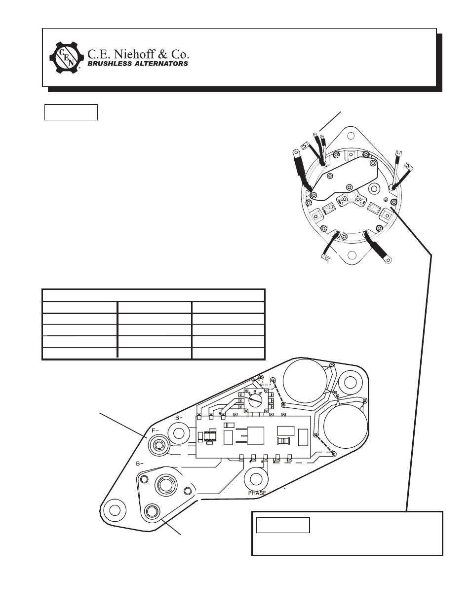
Field Lead
(white wire with ring terminal)
Figure 2 - Series 300 Wiring
“B-” Lead
(heavy black wire)
Field lead white wire with fl ag
terminal must be attached to heat
sink stand-off. There is no terminal on new board for
fi eld lead with fl ag terminal.
NOTICE
This symbol is used to indicate special instructions
on installation, operation or maintenance that are
important but not related to personal injury hazards.
NOTICE
Voltage Select Switch Position
A2-431 Reg. A2-432 Reg. A2-433 Reg.
Position 1—13.8 V
Position 1—27.6 V
Position 1—27.6 V
Position 2—14.2 V
Position 2—28.0 V
Position 2—28.5 V
Position 3—14.6 V
Position 3—28.5 V
Position 3—37.2 V
Position 4—14.6 V
Position 4—29.0 V
Position 4—38.3 V
300 Series – A1-300, A1-301, A1-302, A1-303, A1-305 ,
A1-306, A1-307
N1101, N1102, N1103, N1108, N1111, N1112, N1114 , N1115,
N1117, N1118, N1119, N1120, N1121, N1122, N3017, N3018,
N3037, N3038
1. No modification to cover assembly is needed.
2. New voltage regulator circuit board fits in place of old
one as shown in Figure 1.
3. Wire as shown in Figure 2.
A1-305 and N1114 may have an additional brown lead
(see Figure 1) not required for new regulator. Trim lead
and tape exposed end to insulate from contact with other
components.
Figure 1 - Series 300 Circuit Board
Brown Lead not needed
for new regulator