C.E. Niehoff & Co. C520 Alternator/A2-326 Regulator w/Extended Wiring Harnesses Installation User Manual
Installation instructions
II0117A
Page 1 of 1
A9-4000 & A9-4001 Extended Wiring Harnesses
for Remote-Mounted A2-326 Regulator
with C520 Alternator
Installation Instructions
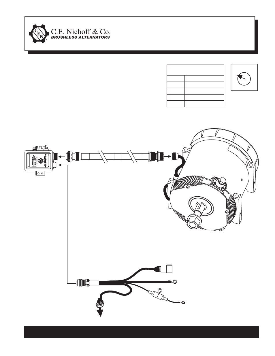
Figure 2 – Remote-Mounted A2-326 Regulator/C520 Alternator with Extended Wiring Harnesses
J1939/11 Connector
C. E. Niehoff & Co. • 2021 Lee Street • Evanston, IL 60202 Tech Services Hotline 800-643-4633
1. Before installing regulator, make sure battery-age switch
on back of regulator is set for appropriate battery age
in years. See Table 1 and Figure 1. Then install regulator
in location determined by vehicle manufacturer.
2. Connect 20-ft. A9-4000 extended wiring harness between
regulator and alternator. Make sure harness plugs are
securely connected to regulator and alternator sockets.
See Figure 2.
3. Using cable ties every 12-14 inches, securely support wiring
harness between alternator and regulator.
4. Connect A9-4001 battery sense harness to J1939 connector on regulator.
5. Complete remaining connections from battery sense harness as shown in Figure 2.
Figure 1 –
4 Battery-Age
Setpoints
1
2 3
4
Connect to battery negative post or busbar
(3/8 dia)
Black wire
Connect to battery positive post or
busbar (3/8 dia)
Red wire
Fuseholder w/1 amp
fuse included
Battery current sensor: current sensor
can be placed on positive or negative
battery cable but battery CHARGING
current should fl ow in direction shown
A2-326 Regulator
A9-4000 Extended wiring harness
C520 Alternator
A9-4001 Battery sense harness
Table 1 — Battery-Age
Setpoints on Regulator
Setpoint
Battery Age (Years)
1
New
2
1
3
2
4
3+