MoTeC PWC Plug-In ECU User Manual
Page 65
58
Appendices
Calibration and Wiring Notes
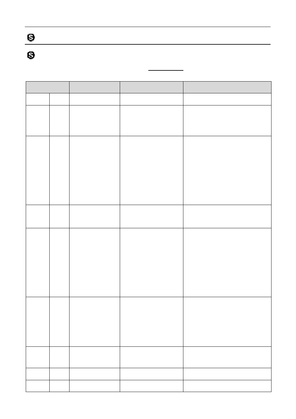
Note 1 – Calibration Functions
The following pins are calibrated in the Base Maps with the function and
parameters as mentioned in the table.
M400 Pin
Sea-Doo Pin
Function
Parameters
Aux1 A18 not used
9: Lambda Heater
Aux2 A01 B29
101: Fuel Pump
Delay 3.0
Polarity 0
Output Mode 0
Aux3 A23 A13,B18
(2004)
3: Aux Table
PWM/Switched 0
Output Mode 0
Polarity 0
Frequency 200
Minimum Duty Cycle 0
Maximum Duty Cycle 100
Hysteresis 0
Aux3 A23 A13,B18
(2006)
0: Off
Aux3 A23 A13,B18
(2007)
107: Driver
Warning
Hold Time 0
Delay to On Time 0.0
Include Diag Errors 0
Logic Polarity 0
Output Mode 0
Power Hold 0
On Alert 1
Aux4 A24 B31
115: Status
Selection 40
Logic Polarity 0
Output Mode 0
Flash 0
Flash Rate 0.0
Aux5 A31 A36
8: Idle Stepper
Max Step Rate 200
Polarity 0
Aux6 A32 A35
0: Off
Aux7 A33 A38
0: Off
MoTeC
with the function and
Parameters
Polarity 0
Output Mode 0
PWM/Switched 0
Output Mode 0
Polarity 0
Frequency 200
Minimum Duty Cycle 0
Maximum Duty Cycle 100
Hysteresis 0
Hold Time 0
Delay to On Time 0.0
Include Diag Errors 0
Logic Polarity 0
Output Mode 0
Power Hold 0
On Alert 1
Selection 40
Logic Polarity 0
Output Mode 0
Flash Rate 0.0
Max Step Rate 200
Polarity 0