MoTeC PWC Plug-In ECU User Manual
Page 50
MoTeC
Appendices
Calibration and Wiring Notes
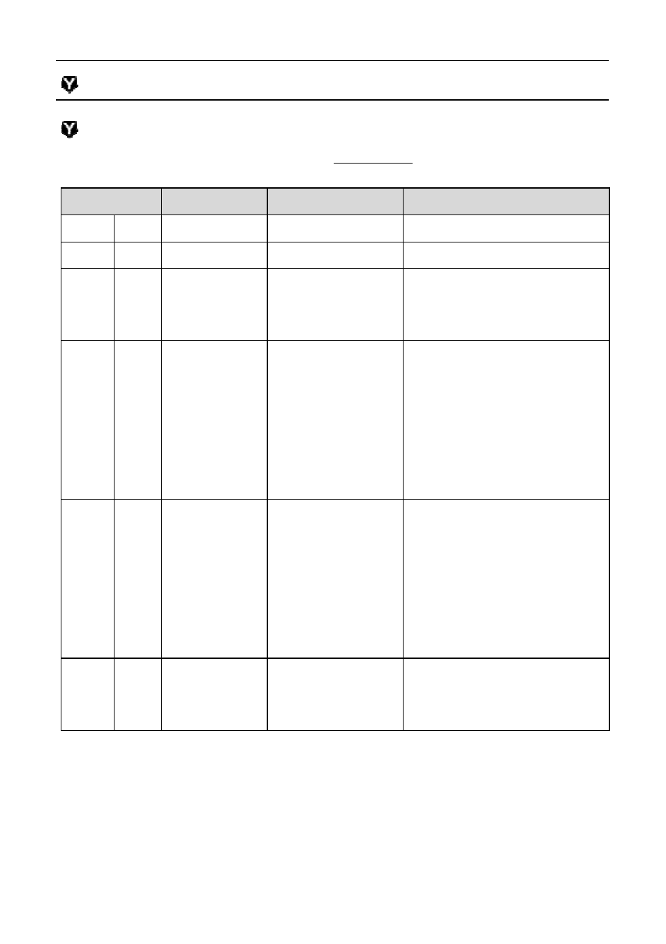
Note 1 – Calibration Functions
The following pins are calibrated in the Base Maps with the function and
parameters as mentioned in the table.
M400 Pin
Yamaha Pin
Function
Parameters
Aux1 A18
R26
5: Drive by wire
Aux2 A01
S26
0: Off
Aux3 A23
S29
101: Fuel Pump
Delay 2.0
Polarity 0
Output Mode 0
Aux4
Aux6
A24
A32
P20
S28
3: Aux Table
PWM/Switched 1
Output Mode 0
Polarity 0
Frequency 10
Minimum Duty Cycle 0
Maximum Duty Cycle 100
Hysteresis 0
Aux8 A34
3: Aux Table
PWM/Switched 0
Output Mode 0
Polarity 0
Frequency
Minimum Duty Cycle 0
Maximum Duty Cycle 100
Hysteresis 0
DIG3 B10
S20
8: Ignition Switch Logic Polarity 1
Delay 0.0
Latch 0
43
with the function and
Parameters
Output Mode 0
PWM/Switched 1
Output Mode 0
Frequency 10
Minimum Duty Cycle 0
Maximum Duty Cycle 100
Hysteresis 0
PWM/Switched 0
Output Mode 0
Frequency 10
Minimum Duty Cycle 0
Maximum Duty Cycle 100
Hysteresis 0
Logic Polarity 1