Appendix f – plm to ecu wiring details, Analog output – MoTeC PLM User Manual
Page 40
40
Appendices
Appendix F – PLM to ECU Wiring Details
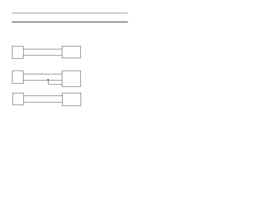
Analog Output
PLM wiring using the Analog Output to M4/M48/M8/M800 ECUs:
Black
F8
F9
31
32
Red
PLM
M4/M48
La+
La -
A out
A out -
(Previously La- was shown connected to ECU 0V, this is now optional)
Black
F8
F9
24A
36A
Red
PLM
M 8
La+
La -
A out
A out -
0V
10A
F8
F9
B25, B12 / 60, 61
B16 / 27
Red
Black
PLM
M800/M880
La1S or La2S
Sensor 0V
A out +
A out
-
CAN
One or more PLMs may be connected to the M800 ECU via the CAN bus.
Note that the ECU version must be V3.0 or higher.
See Appendix H – General CAN Bus Wiring for details on correct wiring and
termination for CAN devices.