Motec 95 – MoTeC M880 User Manual
Page 97
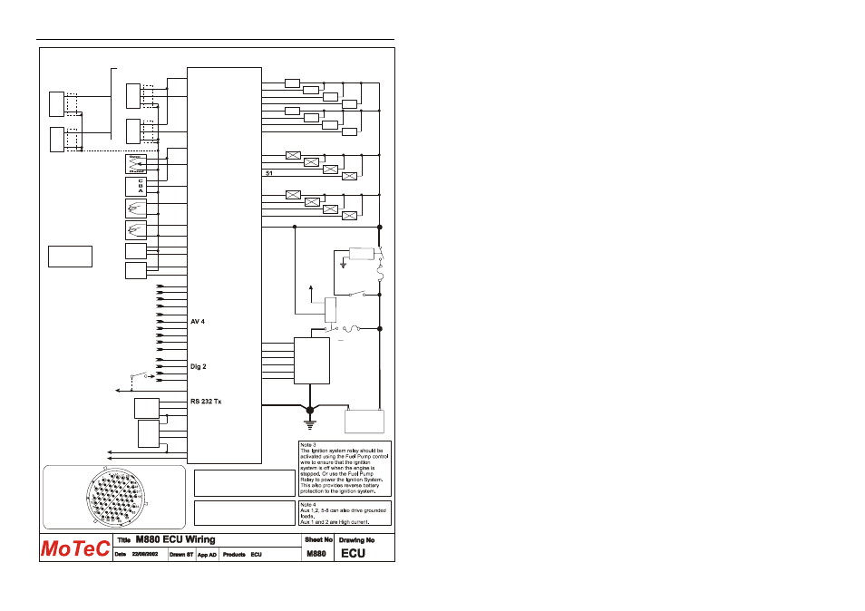
MoTeC
95
REF
(Magnetic)
Manifold
Pressure
Throttle
Position
2
56
49
18
26
AV 2
AV 1
50
AUX OUTPUTS
Stepper Motor, Relays or Valves
Injector 2
Ignition
System
See Detail
Drawings
14,15,19
- +
12 Volt
Battery
Chassis
Earth
12V
GND
20 Amp
Fuse
Refer to the
Trigger Drawings
for details
Sensors
Injectors
ECU
Connect in firing order
for sequential operation
2 nd
33
Injector 1
1 st
63
Injector 3
3 rd
66
Injector 4
4 th
42
Injector 6
6 th
24
Injector 5
5 th
57
Injector 7
7 th
62
Injector 8
8 th
8
Aux 2
9
Aux 1
43
Aux 3
Aux 4
65
Aux 6
59
Aux 5
58
Aux 7
23,32,41
Aux 8
5
Ignition 2
1
Ignition 1
4
Ignition 3
10
Ignition 4
25
Ignition 6
17
Ignition 5
Note 2
Note 3
Note 1
20 Amp
Fuse
+
_
SYNC
(Magnetic)
+
_
REF
(Hall or Optical)
56
49
8V Aux Power
REF
+
_
Sig
SYNC
(Hall or Optical)
+
_
Sig
SYNC
3 8V Eng
Air
Temp
28 AT 1
Engine
Temp
27 0V Eng
Lambda
1
54
LA1P
60
LA1S
Lambda
2
55
LA2P
61
LA2S
5V Eng
16
38 AT 2
34 5V Aux Power
Power to Auxiliary
sensors
0V Aux Power
11
DIGITAL
INPUTS
AT 4
AT 3
AT 5
AT 6
AV 8
30
39
29
37
44
Dig 1
Dig 3
Dig 4
46
45
52
53
ANALOG
TEMP INPUTS
ANALOG
VOLT INPUTS
Ignition
Switch
AV 7
35
AV 3
AV 5
AV 6
6
7
12
36
Note 2
To avoid the fuse blowing due to reverse
battery polarity use a diode activated relay
eg. Bosch 0332 014 112
Note 1
The Fuse is essential to ensure that the
ECU is not damaged by reversed battery
polarity
0V To Auxiliary
Sensors
Looking into
Connector
on ECU
47
48
40
31
13
Note 4
See drawing
X25 for wiring
details
64
Relays or Valves
20,21,22
CAN LO
CAN HI
RS 232 Rx
0V Comms
2
3
5
CAN Connector
Deltron
716-0-0501
1
4
3
5
Serial Connector
D9 female