Ecu inputs & outputs, Main engine sensors, 6 overview – MoTeC M880 User Manual
Page 8
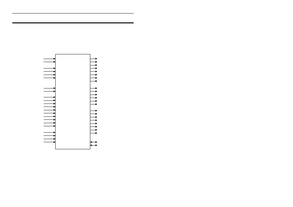
6 Overview
ECU Inputs & Outputs
The ECU analyses signals from the sensors, then controls the Fuel Injectors,
Ignition System and other auxiliary devices according to the Calibration and
Setup Data which is stored in the ECUs programmable memory.
The Inputs and Outputs are shown below.
REF Trigger Sensor
REF
INJ1
Sync Trigger Sensor
SYNC
INJ2
INJ3
Throttle Position Sensor
TP INJ4
MAP INJ5
Engine Temp Sensor
ET INJ6
Air Temp Sensor
AT INJ7
INJ8
Wide Band Lambda Sensor
LA1
Wide Band Lambda Sensor
LA2
IGN1
IGN2
eg. Oil Temp
AT3
IGN3
eg. Fuel Pressure
AT4
IGN4
eg. Fuel Temp
AT5
IGN5
eg. Gear Lever Force
AT6
IGN6
eg. Diff Temp
AV3
eg. Intercooler Temp
AV4
AUX1
eg. Exhaust Temp
AV5
AUX2
eg. Lateral G Force
AV6
AUX3
AV7
AUX4
AV8
AUX5
eg. Driver Fuel Adjustment
AUX6
Manifold Pressure Sensor
eg. Driver Boost Adjustment
AUX7
AUX8
Wheel Speed or Switch
Dig 1
Wheel Speed or Switch
Dig 2
Wheel Speed or Switch
Dig 3
Wheel Speed or Switch
Dig 4
Note: IGN3-6 may be used as
Injector outputs on M800 &
M880 with 10/12 cyl option
A ili
D i
Fuel Injector Outputs
Ignition Outputs
Main Engine Sensors
Optional Sensors
M400/M600/M800/M880
Auxiliary Outputs
Auxiliary Devices such as
Idle Speed Motors
Boost Control Valves
Relays
Warning Lights
etc
RS232 Communications
CAN Communications
Communications
Note: INJ 7&8 not available
on M400 & M600
Note: INJ 5&6 not available
on M400
Note: IGN 5&6 not available
on M400
Main Engine Sensors
The Main Engine Sensors are required for correct operation of the ECU.
The engine RPM is derived from the REF trigger sensor.
The SYNC trigger sensor is required to synchronise the Fuel and Ignition to
the correct engine cycle for sequential injection and correct firing of multicoil
ignition systems.