Appendix d: auxiliary output characteristics – MoTeC M880 User Manual
Page 83
MoTeC
Appendices
81
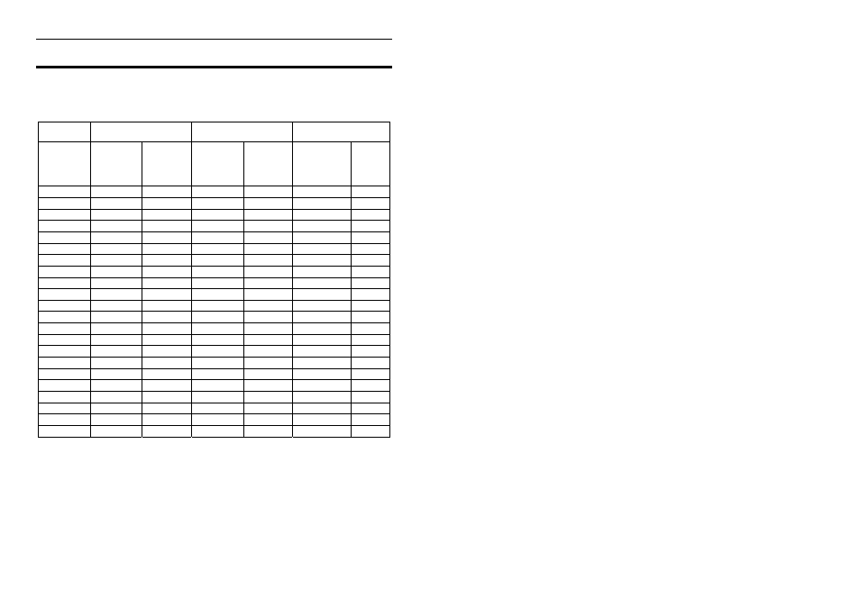
Appendix D: Auxiliary Output Characteristics
The following tables list the characteristics for the Auxiliary Outputs, including
the Ignition and Injector Outputs when used as Auxiliary Outputs.
Output Low Side Driver
High Side Driver General
Nominal
Max
Current
(A)
Min
Current
Limit
(A)
Nominal
Max
Current
(A)
Min
Current
Limit
(A)
Fly-Back
Voltage
(V)
Max
Freq
(Hz)
AUX1
5
7 *
5
7
Recirculate 10000
AUX2
5
7 *
5
7
Recirculate 10000
AUX3
1 3 - - 60V
10000
AUX4
1 3 - - 60V
10000
AUX5
1
3
0.7
0.7 *
Recirculate 200
AUX6
1
3
0.7
0.7 *
Recirculate 200
AUX7
1
3
0.7
0.7 *
Recirculate 200
AUX8
1
3
0.7
0.7 *
Recirculate 200
IGN1
1 3 - - 60V
5000
IGN2
1 3 - - 60V
5000
IGN3
1 3 - - 60V
5000
IGN4
1 3 - - 60V
5000
IGN5
1 3 - - 60V
5000
IGN6
1 3 - - 60V
5000
INJ1
2 4 - - 60V
5000
INJ2
2 4 - - 60V
5000
INJ3
2 4 - - 60V
5000
INJ4
2 4 - - 60V
5000
INJ5
2 4 - - 60V
5000
INJ6
2 4 - - 60V
5000
INJ7
2 4 - - 60V
5000
INJ8
2 4 - - 60V
5000
Normally the current should not exceed the Nominal Max Current but in some
circumstances it may exceed this value for a short period of time as long as it
does not exceed the Min Current Limit and as long as the duty cycle is low.
The limiting factor is thermal dissipation in the output driver.
The total maximum low side current should not exceed 15A.
The minimum frequency for all outputs is 15Hz (except when used as a
switched output).
Items marked * use a linear current limit, all other outputs shutdown at the
current limit.