Bray 70 Series SERVO PRO User Manual
Page 19
17
BRAY Series 70 Servo Pro
Operation and Maintenance Manual
5.1.8 c
ontrol
b
ox
t
erminal
The Servo Pro accepts signals from the optional
Local Control Box which may be mounted integrally or
remotely.
The wiring to the local Control Box is connected at the
factory and should not require any adjustment by the
customer. If a field repair is required, follow the wiring
instructions in Section 5.1.8.1.
The Control Box has the following functions:
Local / Off / Remote Switch:
Local – The Servo Pro responds to position signals
from the local Control Box and ignores the command
signal from the remote process controller
Off – The Servo Pro will not respond to position signals
from either the local Control Box or the command signal
from the remote process controller
Remote – The Servo Pro responds to the command
signal from the remote process controller and ignores
position signals from the local Control Box.
Open / Stop / Close Switch
Open – the Servo Pro powers the actuator motor in the
open direction
Stop – the Servo Pro will stop the actuator motor
Close – the Servo Pro powers the actuator motor in the
closed direction.
5.1.8.1 c
ontrol
b
ox
W
iring
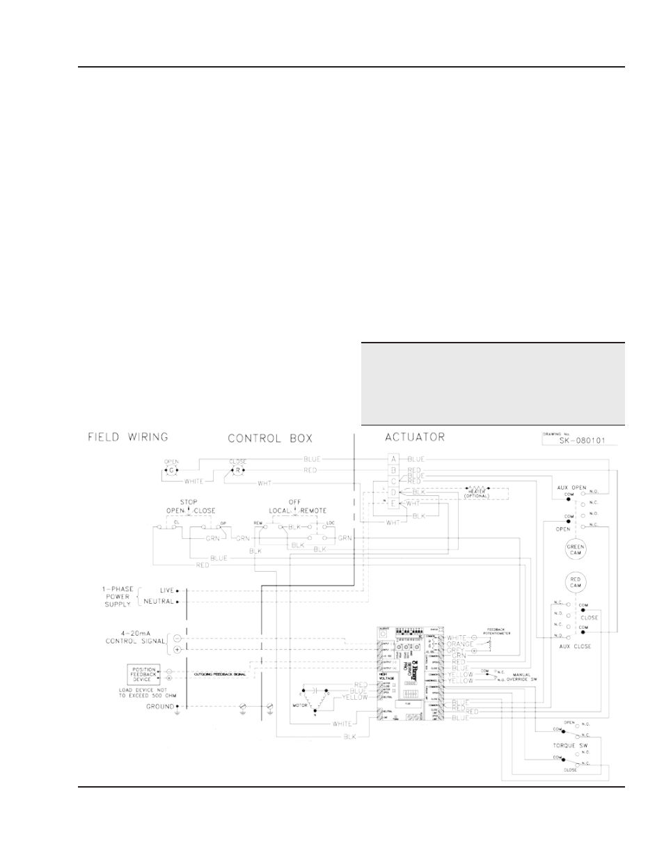
An optional local Control Box can be factory supplied,
or installed and wired in the field according to the wiring
diagram in Figure 5.
For open and close travel limit lamp indication to
function, an optional set of auxiliary travel limit switches
must be installed in the actuator. Please consult the
factory for more details.
notice
The diagram below is for Control Box wiring only; all
other wiring is not shown. Please refer to the complete
wiring diagram on the inside cover of the actuator.
f
igure
5: s
amPle
Wiring
diagram
of
c
ontrol
b
ox
to
s
erVo
P
ro
r
eVision
f
WitH
an
extra
set
of
auxiliary
limit
sWitcHes
for
actuator
end
of
traVel
indication