Mentor 12 – Atec EuroSMC-Mentor-12 User Manual
Page 6
6
MENTOR 12
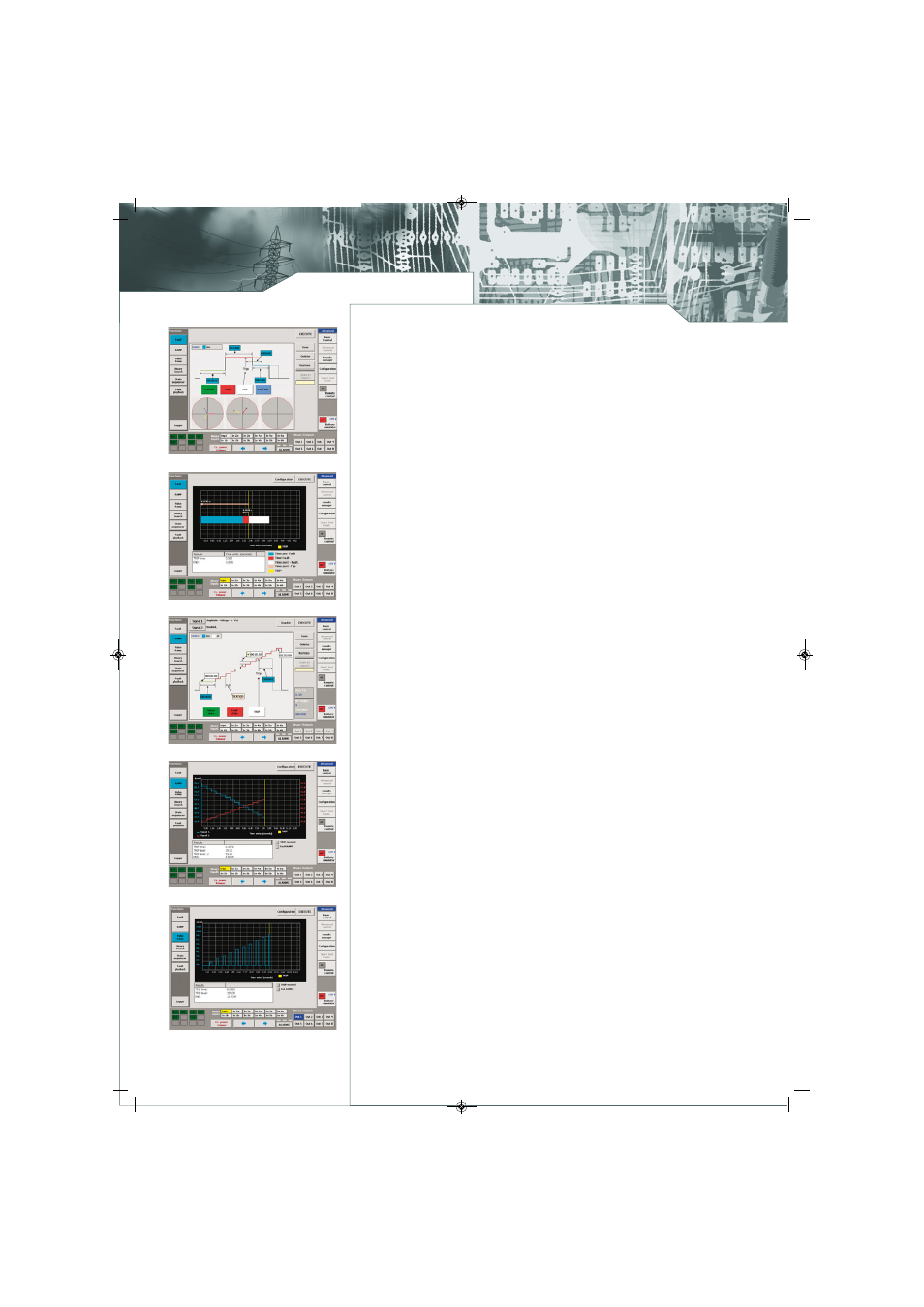
Fault Function
Fault Execution
Ramp Setup
Dual Ramps execution
Pulse Ramp function
ADVANCED TEST FUNCTIONS
The most complete Built-in Test functions, with on-screen graphic configuration, to carry out typical
test for protection relays and protection schemes. These tests allows determining the state of the relay
and obtaining readings and results of different relay parameters under different test conditions,
configured by the user. A Logger is available for all functions, to carry out an in-depth study of the
performance of the relay tested throughout the function.
Fault function: This three-state function allows the user to set a complete simple fault and execute
the prefault, fault and postfault values, including duration of the states, logic I/O states, and trip
conditions. The fault execution displays the progress timeline and test results in graphical and numeric
mode, including the trip time and end function time.
Ramp function: Single and Double Ramps, upward or downward ramps, of any output parameter on
the MENTOR 12 can be programmed and executed. Ramp function operation is provided for finding
limiting values, such as pick-up and drop-off. The linear ramp is the best way of handling parameters
such as the Phase Angle, Voltage and Frequency, especially the latter, as the real performance of these
parameters can be reproduced with great precision.
The flexibility of this module allows two synchronized simultaneous ramps of different variables, each
one applied to different types of output quantities. For example, one ramp moving the Voltage and
the other moving the Current (Impedance ramp), or applied to the same selected output source.
For example one ramp moving the voltage and the other moving the frequency at the same time ( V/Hz
variation ramp).
After ramp and trip conditions are set, the test progress is displayed in an oscillographic fashion, with
electrical values evolving along the ramp and trip events being stamped on the timeline as they take
place. Relay trip time, trip value and duration of the test are displayed, and test repetition can also
be performed if desired, or with different conditions. At the end of a test, user can type a name and
a brief description and save it for future use. Since storage takes place on removable USB pendrives,
the capacity is unlimited, and it also provides a way to create a collection of automatic test routines.
Pulse Ramp function: It is a way of carrying out a Fault ramp, each state with its pre-fault and its fault.
The basic difference is that instead of continuously increasing the magnitude, a preset condition state
occurs between consecutive pulses. This function is preferably used when instantaneous or defined
time values are sought in Overcurrent elements, as it enables to inject a high current value during a
specified time and return to low current conditions or even non-existing current conditions between
each programmed pulse, thus eliminating the possibility of damaging the relay tested.
It is also very useful to verify trip setting values in protection zones, as we can enter the zone for a defined
time and exit it without causing the other slower zones to trip.
The information about the number of steps (increases) and the total function length (in milliseconds)
appears automatically calculated in the screen, as in the ramp function.
Binary Search function, unlike the ramps, the Binary Search does not use a fixed increase value, as
it adapts to different values to make an effective search. The Binary Search function is designed to
cover the circumstance when you do not know the trip value or even, to verify a known trip value carrying
out the test in a different way.
State Sequencer function: The State Sequencer is a very flexible test module to test protection schemes,
since it allows programming a sequence of all the outputs available on the MENTOR, analog or binary,
as you desire, in a logical sequence of states. The State Sequencer is used to test protection functions
that are closely connected to times and actions dependent on each other, such as reclosing cycles,
protection schemes with segregated or selective trips, sending orders and signals to other protections,
communication schemes, etc. To use this function it is important to study the data contained in the
Logger in detail as well as their correlation with the changes in state, depending on what the protection
or scheme tested are expected to do under the injected conditions.
Within one state, all configured test signals (voltage and current outputs) of the test device can be
set independently in amplitude, phase, and frequency.
Mentor12 EN v3_SMC fichas 09/08/13 15:09 Página 6