Atec Megger-MPRT8445 User Manual
Page 6
MPRT
Megger Protective Relay Test System
6
I
Universal input voltage - Operating from 90 to 264
Vac, 50/60 Hz, the MPRT can use virtually any standard
source in the world.
I
Battery simulator - MPRT’s battery simulator provides
dc output voltages of 24, 48, 125 and 250 Volts.
Eliminates needing a separate dc source for providing
logic voltage for microprocessor-based relays.
I
Immediate error indication - Audible and visual
alarms indicate when amplitude or waveforms of the
outputs are in error.
I
Modular design - Output modules plug-in and slide
out easily for system re-configuration and maintenance.
I
Ancillary Interface - Provides interface to other MPRT
units.
I
MPRT Model 8430 - Provides up to 300 Volts rms. at
150 VA and 30 Amps rms. at 200 VA per phase. Ample
voltage for testing high instantaneous overvoltage relays.
The current amplifier has high compliance voltage at
low currents for testing ground overcurrent relays. When
configured with four channels, the current amplifiers can
be paralleled to provide a maximum of 120 Amperes at
800 VA, for testing instantaneous overcurrent relays.
With high VA output ratings, the unit can be used for
testing a panel of relays.
I
MPRT Model 8415 - Provides up to 150 Volts rms. at
150 VA and 15 Amps rms. at 200 VA per phase. This
lower cost unit is ideal for testing relays used with 1
Amp secondary CT’s. The current amplifier has high
compliance voltage at low currents for testing ground
overcurrent relays. When configured with four channels,
the current amplifiers can be paralleled to provide a
maximum of 60 Amperes at 800 VA, for testing
instantaneous overcurrent relays. With high VA output
ratings, the unit can be used for testing a panel of
relays.
SPECIFICATIONS
Input Power
100 to 240 Volts, ±10%, AC, 1Ø, 50/60 Hz, 2100 VA.
Outputs
All outputs are independent from sudden changes in line voltage
and frequency. This provides stable outputs not affected by
sudden changes in the source. All outputs are regulated so
changes in load impedance do not affect the output. Each output
module consists of one current amplifier, and a voltage amplifier.
The voltage amplifier may be converted to a current source.
Therefore, one amplifier module may be used to test current
differential relays, including harmonic restraint.
Output Current
The following specifications cover both Model 8430 and Model
8415 modules. Outputs are rated with the following:
Model 8430
Per phase:
Output Current
Power
Max V
4 Amperes
200 VA
50.0 Vrms
7.5 Amperes
200 VA
26.7 Vrms
15 Amperes
200 VA
13.4 Vrms
30 Amperes
200 VA
6.67 Vrms
DC
200 Watts
With two currents in parallel:
Output Current
Power
Max V
8 Amperes
400 VA
50.0 Vrms
15Amperes
400 VA
26.7 Vrms
30 Amperes
400 VA
13.4 Vrms
60 Amperes
400 VA
6.67 Vrms
With three currents in parallel:
Output Current
Power
Max V
12 Amperes
600 VA
50.0 Vrms
22.5Amperes
600 VA
26.7 Vrms
45 Amperes
600 VA
13.4 Vrms
90 Amperes
600 VA
6.67 Vrms
With four currents in parallel:
Output Current
Power
Max V
16 Amperes
800 VA
50.0 Vrms
30 Amperes
800 VA
26.7 Vrms
60 Amperes
800 VA
13.4 Vrms
120 Amperes
800 VA
6.67 Vrms
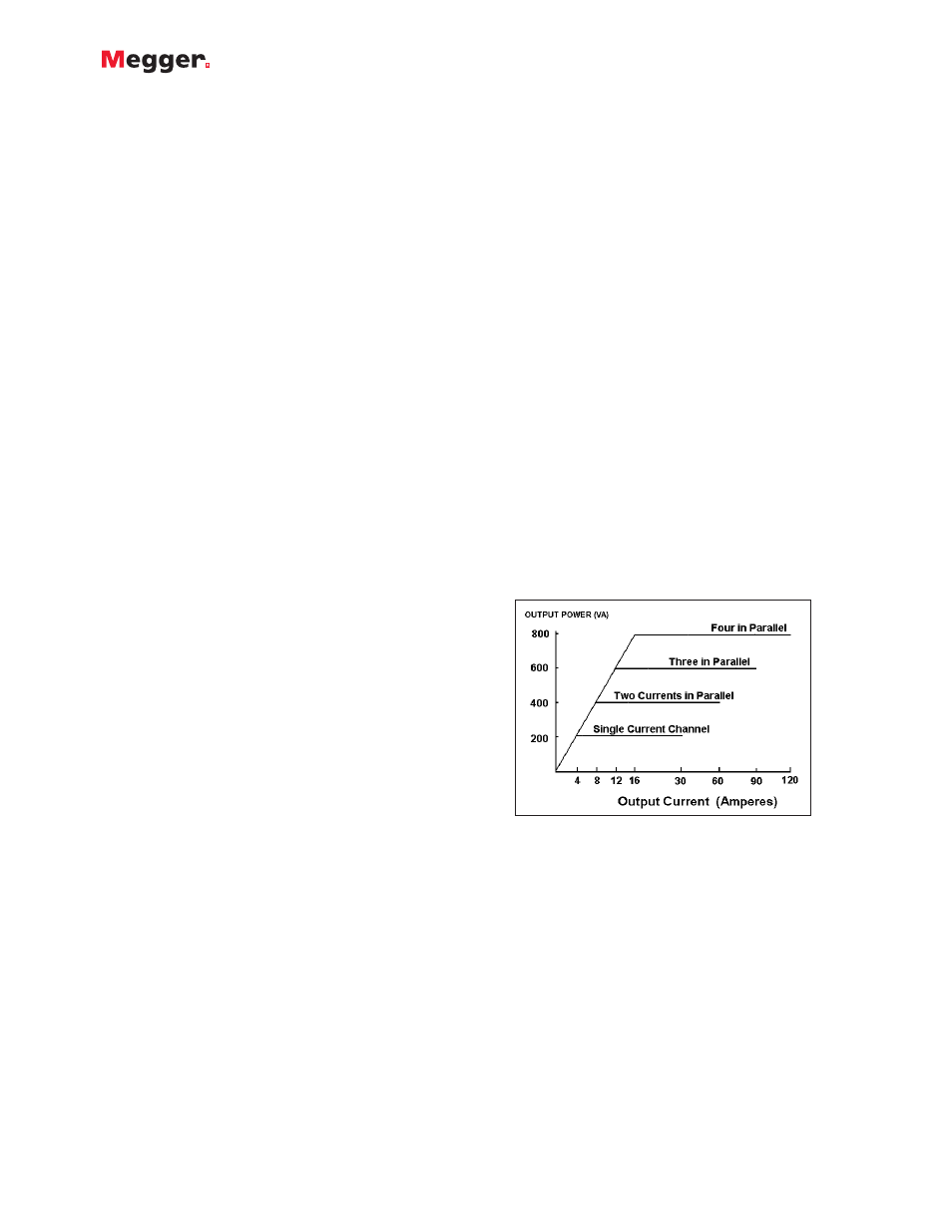
Power Curve for Model 8430
With two currents in series, the compliance voltage doubles to
provide 4.0 Amperes at 100 Volts.
Model 8415
Per phase:
Output Current
Power
Max V
4 Amperes
200 VA
50.0 Vrms
7.5 Amperes
200 VA
26.7 Vrms
15 Amperes
200 VA
13.4 Vrms
DC
200 Watts
With two currents in parallel:
Output Current
Power
Max V
8 Amperes
400 VA
50 Vrms
15 Amperes
400 VA
26.7 Vrms
30 Amperes
400 VA
13.4 Vrms