Avts 3.0 – Atec Megger-MPRT8445 User Manual
Page 10
10
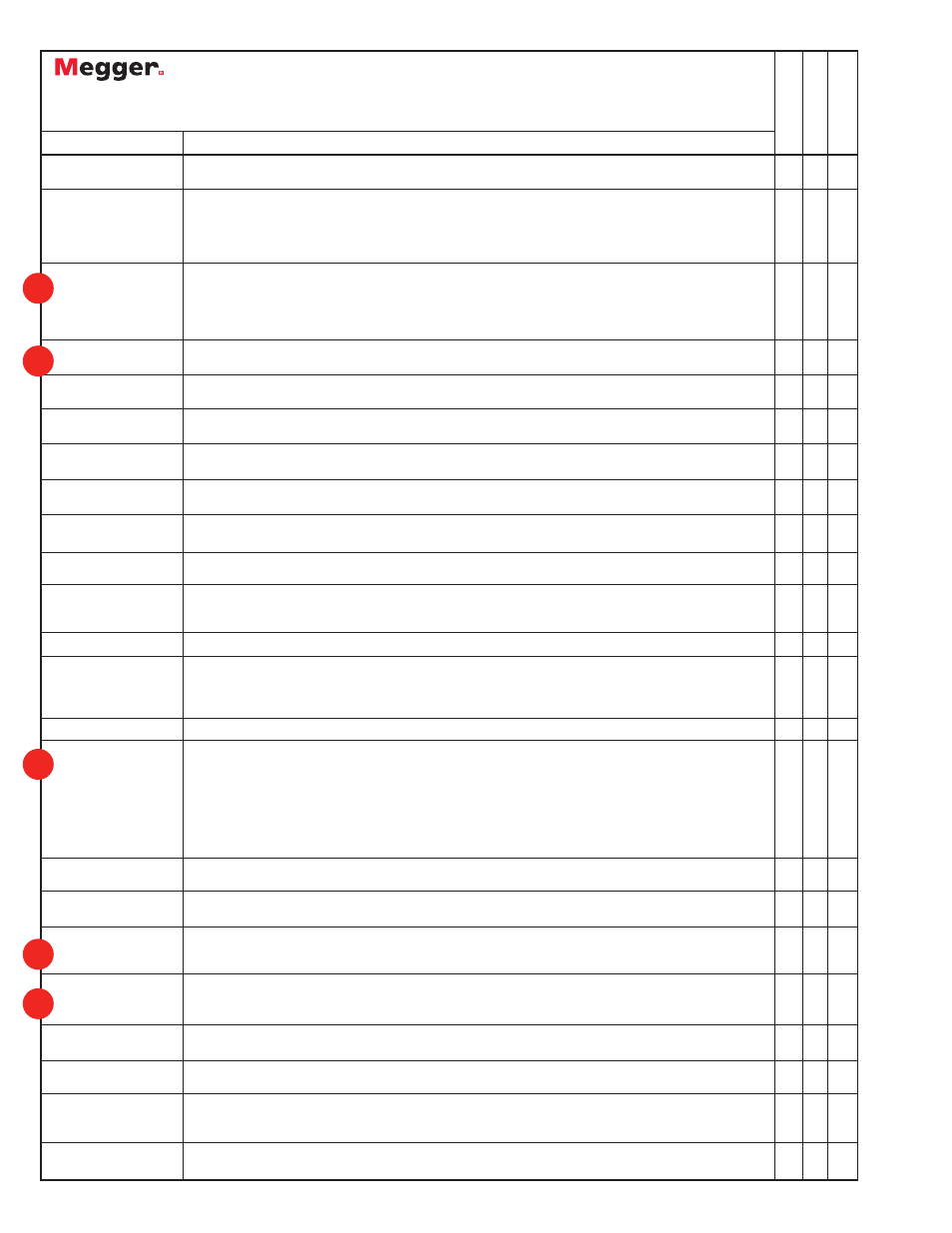
Online Vector Control
Online Ramp Control
On-Line Click On Fault
RIO File Format
DFR Playback
Fault Calculator
Import, Save, and
Execute Test Modules
Overcurrent Wizard
Over/Under Voltage
Wizard
Distance Wizard
Differential Wizard
Directional Wizard
Transducer Testing
with Touch-View
Interface or AVTS soft-
ware
Test Editor
Dynamic Control
Basic Programming
Tool
One-Touch Test™
Modbus
SS1 File Converter
Import Aspen Relay
Database
®
End-to-End Test Macro
Waveform Digitizer
DFR Waveform Viewer
and Playback
The Online Vector Control allows the user to have direct control of the Relay Test System. Up to sixteen
vector states may be created and sequenced back through the test system.
Preramp (prefault), Ramp 1 and Ramp 2 are available for use to be played back through the test system.
Automatically Ramp or Pulse Ramp outputs. PulseRamp provides the capability to determine reach points
on multi-zone distance relays without having to defeat the zone timing elements, and provides pre-fault
load conditions for relays that require it. Enable timer control with either ramp. PulseRamp is available
down to the basic level.
The user can define the type of operating characteristic using the AVTS Theoretical Control or Import files
in the RIO file format, then click at a point on the characteristic that they wish to test for, either as a Shot,
a Check Point or using the Search features. If using the Search the test will progress down a line, using
click and drag, either as a ramp or a pulse ramp looking for the relay to operate. Test results appear in
the RX diagram along with the theoretical operating characteristic of the relay.
Used to download relay characteristic settings from certain manufacturers microprocessor based relays for
full automatic testing using Click-On-Fault either On Line or in the Test Editor Screen.
Import and execute relay test modules, which contain DFR playback files created using the DFR Waveform
Viewer Tool.
Calculate fault values for Ш-Ш, Ш-N, and 3 Ø faults. Use line voltage, line Z and angle, relay volts and
angle, relay amps and Z0/Z1.
Import relay test files and execute selected tests. Save results to built-in Microsoft Access compatible data
base, and print results.
Provides automatic testing of overcurrent relays, including pickup, timing characteristic using IEEE / IEC
formulas, Instantaneous, DC target and seal-in tests.
Provides automatic testing of over and under voltage relays, including pickup, timing characteristic and DC
target and seal-in tests.
Provides automatic testing of distance relays. Ш-Ш, Ш-G, and 3 Phase faults are available. Test result
graphics are displayed in an R X plane.
Provides automatic testing current differential relays, including pickup, slope (includes capability to control
up to 8 currents for differential characteristic), and 2nd, 3rd and 5th harmonic restraint tests on transformer
differential relays.
Provides automatic testing capability of directional elements.
Use the TVI to do manual testing of all types of transducers. Results maybe saved to the internal memory,
downloaded to AVTS and printed later. AVTS users may create a test for any type transducer using the Test
Editor Screen and the Analog Input control tool.
Provides editing tools for modifying tests.
Accessed through the Test Editor Screen, the Dynamic Control provides dynamic multi-state testing of
relays with more flexibility and choices than Vector Control. A "state" can be voltage(s), current(s), phase
angle(s), timers, start and stop the analog recorder, set Boolean logic for the binary inputs, set binary
output(s), or even use variables to set values. The test transitions from one state to another after a
programmed time delay of either milliseconds or cycles, or after a trigger condition. In addition, the
Dynamic Control allows the user to easily build harmonic waveforms with frequencies up to 1000 Hz. In
conjunction with the Dynamic Control the Capture feature may be used to measure and display the output
analog waveforms, binary inputs and outputs to evaluate the dynamic test results in a graphic form.
Provides control tool in the Test Editor. Basic programs can be written using the test system command set
for special testing applications.
Test Editor control tool, used in conjunction with specific Megger Test Modules, to download relay settings
(into the AVTS settings screen) from microprocessor based relays for full automatic one-touch testing.
Used in conjunction with specific Megger Test Modules to automatically download relay settings (into the
AVTS setting screen) from microprocessor based relays, which use the Modbus protocol, for full automatic
one-touch testing.
SS1 files are generated using Power System Simulation software programs by Electrocon
®
CAPE™ or Aspen
One-liner
®
. By modeling the power system and using the SS1 files, the relay can then be tested
dynamically using realistic system test scenarios.
Capability to import relay settings directly from Aspen Relay Database
®
“End-to-End” testing is used to describe the testing of an entire line protection scheme. This includes all
protective relays, interface equipment, and any communication equipment.
Provides digitizing tools to create digital time curves for old electromechanical relay time curves (that do
not fit any time curve algorithm) up to the most complex relay operating characteristics. Good for
digitizing scanned waveforms (like from a light-beam chart recorder).
Import, view, modify and replay Digital Fault Recordings or EMTP/ATP simulations that are in the
COMTRADE file format.
I
I
I
I
I
I
I
I
I
I
I
I
I
I
I
I
I
I
I
I
I
I
I
I
I
I
I
I
I
I
I
I
I
I
I
I
I
I
I
I
I
I
I
I
I
I
I
I
I
I
I
I
I
I
I
I
AVTS 3.0
Basic
Advanced
Pr
ofessional
Feature
Description
NEW
NEW
NEW
NEW
NEW