Atec Megger-MPRT8445 User Manual
Page 15
MPRT
Megger Protective Relay Test System
15
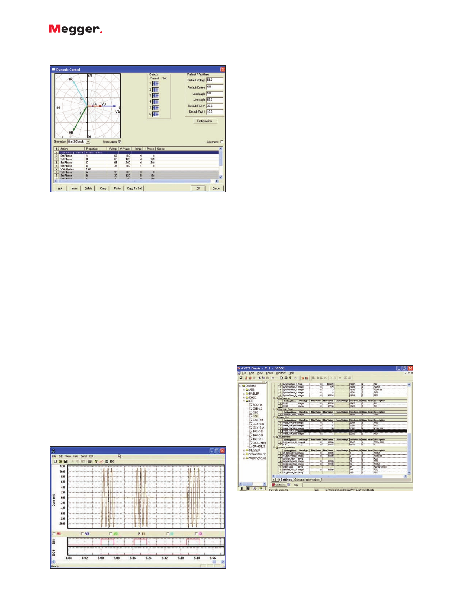
Dynamic Control Screen
The Dynamic Control, accessed from the Test Editor
Screen, provides the user an easy means of settings up
multi-state dynamic tests that are normally associated with
trip and reclosing schemes. The figure above shows an
example test setup using the Dynamic Control.
A “state” can be voltage(s), current(s), phase angle(s),
timers, start and stop the analog recorder, set Boolean
logic for the binary inputs, set binary output(s), or even
use variables to set values. The test transitions from one
state to another after a programmed time delay of either
milliseconds or cycles, or after a trigger condition. In
addition, the Dynamic Control allows the user to easily
build harmonic waveforms with frequencies up to 1000
Hz. In conjunction with the Dynamic Control the Capture
feature may be used to measure and display the output
analog waveforms, binary inputs and outputs to evaluate
the dynamic test results in a graphic form.
Dynamic Analog Recorder
In association with the Dynamic Control is an analog
recorder, which not only records the action of the binary
inputs and outputs, but it also records the actual analog
waveforms of the outputs. For example, after running a
reclosing sequence press OK to view the waveform
capture screen. When the Waveform Capture screen
comes up, press the Lightning Bolt button. This will load
the data from the MPRT resulting in something like the
following example.
General Electric UR G60 Modbus Device Setting Screen
Dynamic Control
The user can view the actual outputs waveforms as well as
any selected binary inputs and or binary output contacts.
This capability also will work with Multi-State or State
Sequence Playback. It should also be noted that the user
can record the complex waveforms that they applied using
the harmonic waveform generator in the dynamic control.
Basic Programming Tool
The Basic Programming Tool provides a means to either
import older test macros into AVTS and execute legacy test
files, or to send the test system syntax commands to do
special test applications not covered by the standard test
modules, generic test modules, wizards, DFR playback,
vector control, ramp control or dynamic control. These
commands can be issued from the Basic Tool icon as part
of a special test file.
Modbus Communications
AVTS now has the capability to communicate with relays
via the Modbus protocol. This allows the AVTS user the
ability to automatically download relay settings from the
relay via the Modbus addressing scheme into the AVTS
relay setting screen. In addition AVTS can now monitor the
relay protection or metering elements via the Modbus
communications. This means the user will not need to
change the relay outputs, thus test the relay without
making any changes to the relay what so ever. Instead of
the user having to read the meter values and manually
input them into a result screen the software can now read
the values automatically. This feature combined with the
Sequence Test feature can mean fully automatic testing
without user intervention. As an example, the General
Electric UR Model G60 relay device settings screen can be
seen in the following figure. Note the Modbus address for
each setting in the relay is defined in the Device Setting
screen. Once the device setting screen is created for the
relay, test files may be created.
Dynamic Recorder Screen for Single Phase Multi-Shot Reclosing Relay