Digital analyzer (option upl-b2 or -b29) – Atec Rohde-Schwarz-UPL User Manual
Page 18
18
Audio Analyzer UPL
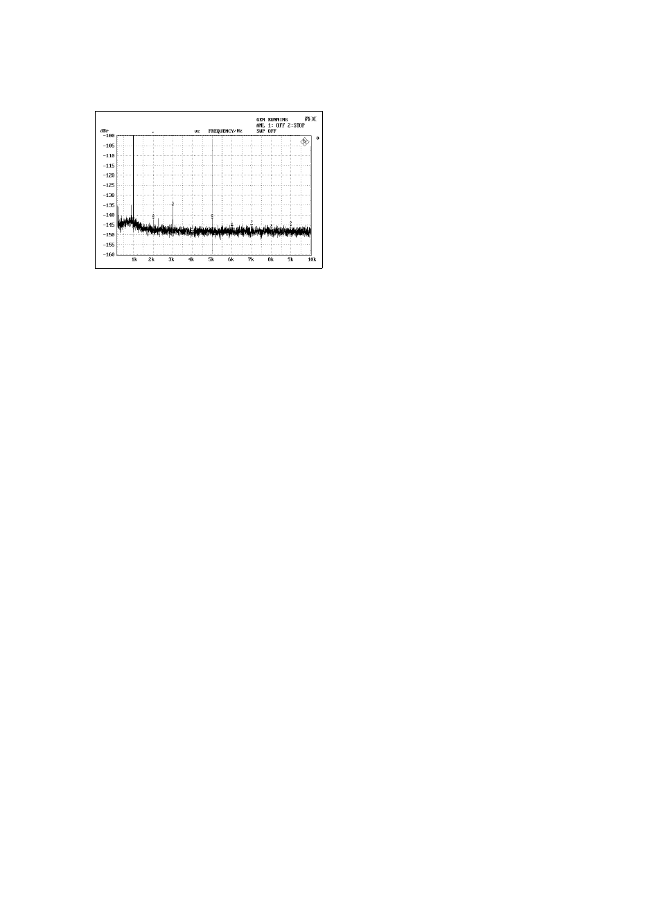
Typical spectrum of low distortion generator at 1 kHz, 1 V
MOD DIST
for measuring the modulation distortion
Frequency range lower frequency
30 Hz to 2700 Hz
upper frequency
8 x LF to 21.75 kHz
Level ratio (LF:UF)
selectable from 10:1 to 1:1
Level accuracy
±
0.5 dB
Inherent distortion
<
–94 dB (typ. –100 dB) at 7 kHz, 60 Hz
<
–84 dB (typ. –90 dB),
level ratio LF:UF = 4:1
Sweep parameters
upper frequency, level
DFD
for measuring the difference tone
Frequency range difference freq.
80 Hz to 2 kHz
center frequency
200 Hz to 20.75 kHz
Level accuracy
±
0.5 dB
Inherent distortion
1)
DFD d
2
<
–114 dB, typ.–120 dB
DFD d
3
<
–92 dB, typ. –100 dB
Sweep parameters
center frequency, level
Multi-sine
Frequency range
2.93 Hz to 21.75 kHz
Frequency spacing
adjustable from 2.93 Hz
Frequency resolution
<0.01% or matching FFT frequency
spacing
Dynamic range
100 dB, referred to total peak value
Characteristics
Mode 1
1 to 17 spectral lines
– level and frequency selectable for
each line
– phase of each component optimized
for minimum crest factor
– phase of each component or
crest factor selectable (with UPL-B6)
Mode 2
1 to 7400 spectral lines (noise in fre-
quency domain), distribution: white,
pink, 1/3 octave, defined by file; crest
factor selectable (with UPL-B6)
Sine burst, sine
2
burst
Burst time
1 sample up to 60 s, 1-sample resolu-
tion
Interval
burst time up to 60 s, 1-sample res.
Low level
0 to burst level, absolute or relative to
burst level (0 with sine
2
burst)
Bandwidth
21.75 kHz (elliptical filter)
Sweep parameters
burst frequency, level, time, interval
Noise
Distribution
Gaussian, triangular, rectangular
Arbitrary waveform
loaded from file
File format
*.TTF (internal)
memory depth max. 16 k
*.WAV
2)
reproduction of audio files
(mono), duration approx. 10 s per
Mbyte RAM
Clock rate
48 kHz
Bandwidth
21.75 kHz (elliptical filter)
1)
Center frequency >5 kHz, difference frequency <1 kHz;
DFD d2 –100 dB (typ.) with DC offset.
2)
With UPL-B29 only in base rate mode.
Polarity test signal
Sine
2
burst with following characteristics:
Frequency
1.2 kHz
On-time
1 cycle (0.8333 ms)
Interval
2 cycles (1.6667 ms)
FM signal
Carrier frequency
2 Hz to 21.75 kHz
Modulation frequency
1 mHz to 21.75 kHz
Modulation
0% to 100%
AM signal
Carrier frequency
2 Hz to 21.75 kHz
Modulation frequency
1 mHz to 21.75 kHz
Modulation
0% to 100%
DC voltage
Level range
0 V to
±
10 V (
±
5 V unbalanced),
sweep possible
Accuracy
±
2%
DC offset
3)
0 V to
±
10.0 V (
±
5 V unbalanced)
Accuracy
±
2%
Residual offset
<
1% of rms value of AC signal
Digital analyzer (option UPL-B2 or -B29)
Frequency limits specified for measurement functions apply to a sampling rate
of 48 kHz. For other sampling rates limits are calculated according to the for-
mula: f
new
= f
48 kHz
x sampling rate/48 kHz.
Inputs
Balanced input
XLR connector, transformer coupling
Impedance
110
Ω
Level (V
PP
)
min. 200 mV, max. 12 V
Unbalanced input
BNC, grounded
Impedance
75
Ω
Level (V
PP
)
min. 100 mV, max. 5 V
Optical input
TOSLINK
Channels
1, 2 or both
Audio bits
8 to 24
Clock rate
35 kHz to 55 kHz with UPL-B2 or
UPL-B29 in base rate mode
35 kHz to 106 kHz with UPL-B29 in
high rate mode
synchronous to DAI or DARS
Format
professional and consumer format to
AES3 or IEC-958 as well as user-defin-
able formats at all inputs
Measurement functions
All measurements at 24 bits, full scale
RMS value, wideband
Measurement bandwidth
up to 0.5 times the clock rate
Accuracy
AUTO FAST
±
0.1 dB
AUTO
±
0.01 dB
FIX
±
0.001 dB
Integration time
AUTO FAST/AUTO
4.2 ms/42 ms, at least 1 cycle
VALUE
1 ms to 10 s
GEN TRACK
2.1 ms, at least 1 cycle
Filter
weighting filters and user-definable fil-
ters, up to 3 filters can be combined
Spectrum
post-FFT of filtered signal
RMS value, selective
Bandwidth (–0.1 dB)
1%, 3%, 1/12 octave, 1/3 octave
and user-selectable fixed bandwidth,
min. bandwidth 20 Hz
Selectivity
100 dB, bandpass or bandstop filter,
8th order elliptical filter
3)
No DC offset for signal generation with Low Dist ON. With DC offset the AC
voltage swing will be reduced, specified inherent distortion values apply to
DC offset = 0.