Digital generators, Digital audio outputs (r&s, Upv-b2 option) – Atec Rohde-Schwarz-UPV User Manual
Page 15: S output (r&s, Upv-b41 option)
Version 03.00, August 2011
Rohde & Schwarz R&S
®
UPV Audio Analyzer 15
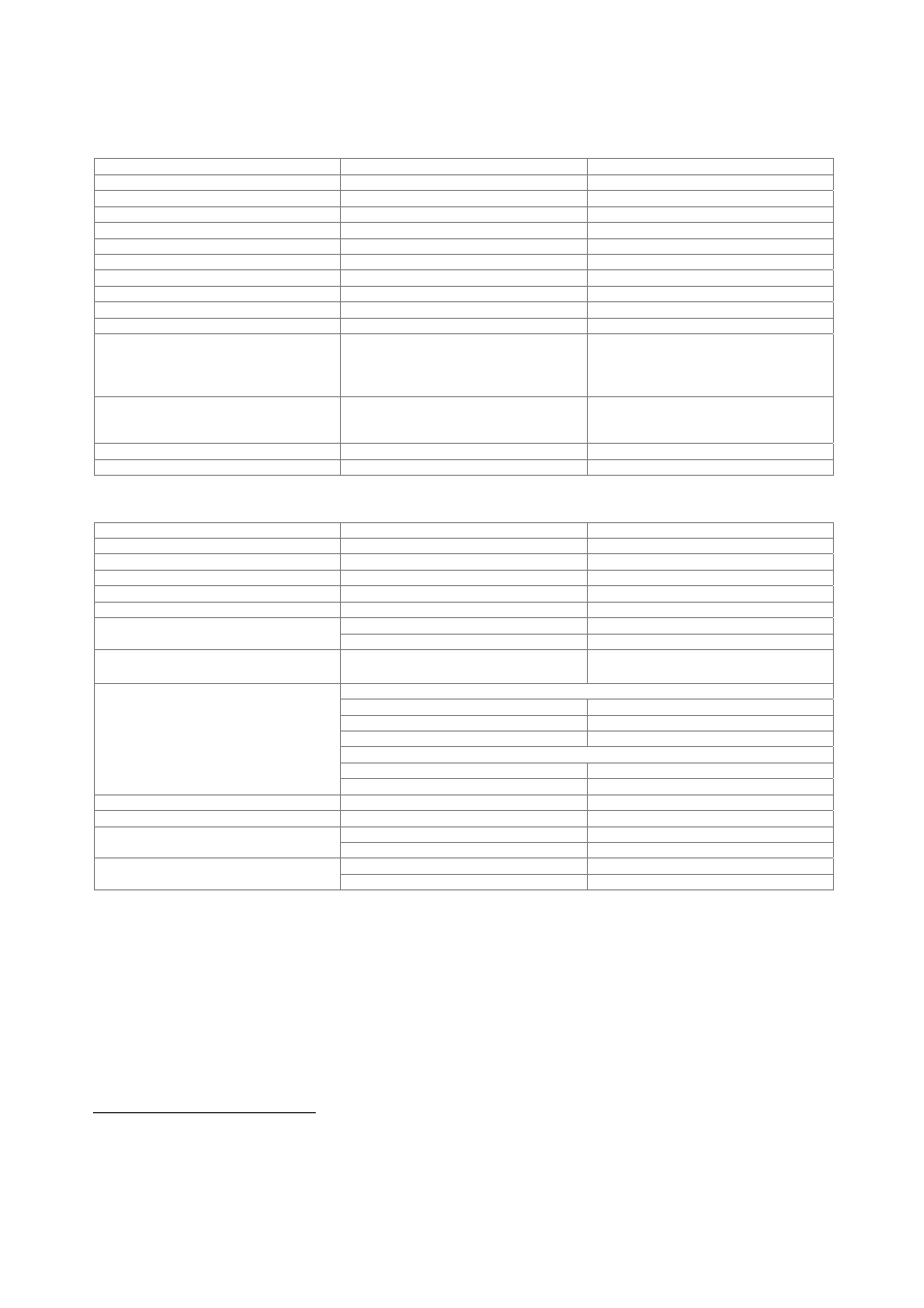
Digital generators
Digital audio outputs (R&S
®
UPV-B2 option)
Balanced output
XLR connector, transformer coupling
Impedance
110
Ω, short-circuit-proof
Level (peak-peak)
into 110 Ω
0 V to 8 V, in 240 steps
Level error
RMS
±1 dB
Unbalanced output
BNC, transformer coupling
Impedance
75
Ω, short-circuit-proof
Level (peak-peak)
into 75 Ω
0 V to 2 V, in 240 steps
Level error
RMS
±1 dB
Optical output
TOSLINK
Channels
1, 2 or both
Audio bits
8 to 24
Clock rate
internal: generator clock or
synchronization to analyzer
external: synchronization to word clock
input, DARS
30 kHz to 200 kHz
Format
professional and consumer format in line
with AES3 or IEC 60958 as well as user-
definable formats at all outputs
Phase (output to reference)
adjustable
between
−64 UI and +64 UI
Cable simulator
100 m typical audio cable
I
2
S output (R&S
®
UPV-B41 option)
Output
25-pin D-Sub connector (male)
Impedance
50
Ω
, short-circuit-proof
Level
3.3 V
Channels
1, 2 or both multiplexed
Word length
16 bit/24 bit/32 bit per channel
Audio bits
8 to 32
word length 16 bit/32 bit
6.75 kHz to 400 kHz
Word clock rate
word length 24 bit
6.75 kHz to 200 kHz
Synchronization
internal
clock
external word clock or master clock
sync to internal clock, external word clock
word length 16 bit
64, 128, 256, 512
word length 24 bit
96, 192, 384
word length 32 bit
128, 256, 512
sync to external master clock
word length 16 bit/32 bit
128, 256, 512
Master/word clock ratio
13
word length 24 bit
192, 384
Master clock rate
432 kHz to 51.2 MHz
Clock input (TX CLK IN)
BNC
low
< 0.8 V (min. –5 V)
Level
high
> 2 V (max. +10 V)
level –0.5 V to +5.5 V
10 kΩ
Impedance
level –5 V to –0.5 V or +5 V to +10 V
100 Ω
13
Master clock max. 51.2 MHz.