Digital analyzers, Digital audio inputs (r&s, Upv-b2 option) – Atec Rohde-Schwarz-UPV User Manual
Page 11: S input (r&s, Upv-b41 option), Universal serial interface input (r&s, Upv-b42 option)
Version 03.00, August 2011
Rohde & Schwarz R&S
®
UPV Audio Analyzer 11
Digital analyzers
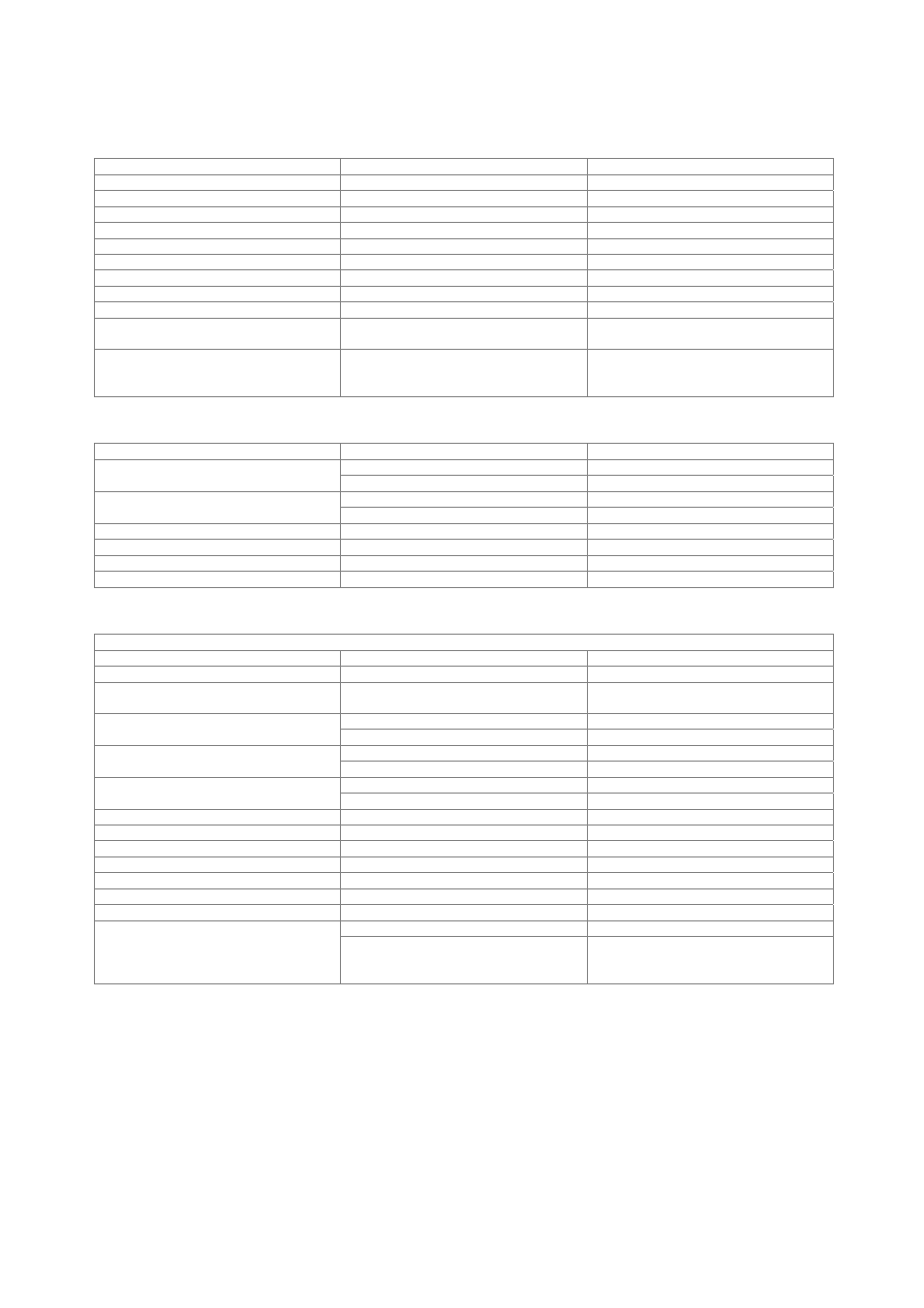
Digital audio inputs (R&S
®
UPV-B2 option)
Balanced input
XLR connector, transformer coupling
Impedance
110
Ω
Level
peak-peak
200 mV to 12 V
Unbalanced input
BNC,
grounded
Impedance
75
Ω
Level
peak-peak
100 mV to 5 V
Optical input
TOSLINK
Channels
1, 2 or both
Audio bits
8 to 24
Clock rate
30 kHz to 200 kHz
Format
professional and consumer format in line
with AES3 or IEC 60958
Reclocking
input signal sampled with low-jitter clock
signal and available at AUX output
(XLR connector on rear panel)
I
2
S input (R&S
®
UPV-B41 option)
Input
25-pin D-Sub connector (male)
low
< 0.8 V (min. –5 V)
Level
high
> 2 V (max. 10 V)
level –0.5 V to +5.5 V
10 kΩ
Impedance
level –5 V to –0.5 V and +5 V to +10 V
100 Ω
Channels
1, 2 or both multiplexed
Word length
16 bit/24 bit/32 bit per channel
Audio bits
8 to 32
Word clock rate
6.75 kHz to 400 kHz
Universal serial interface input (R&S
®
UPV-B42 option)
Interface format
Connector
26-pin connector strip, 2.54 mm (female)
Input data lines
4
Data routing
any input data line to any measurement
channel
dual-channel analyzer mode
1 or 2
Input measurement channels
eight-channel analyzer mode
1 to 8
single-sample format
1
Samples per frame
multisample format
2 to 32
single-sample format
1 to 256
Number of slots
multisample format
up to 32
Slot length
8 bit to 256 bit
Frame length
slot length × number of slots
8 bit to 2048 bit
Lead bits
0 to (slot length – audio bits)
Audio bits
8 to 32
Audio bit order
MSB or LSB first
Audio bit decoding mode
linear PCM, A-law, µ-law
Clock mode
continuous clock, gated clock
internal
internal clock source
Synchronization
external frame
sync,
frame sync and bit clock,
master clock