Atec Agilent-N5181B-N5182B User Manual
Page 21
21
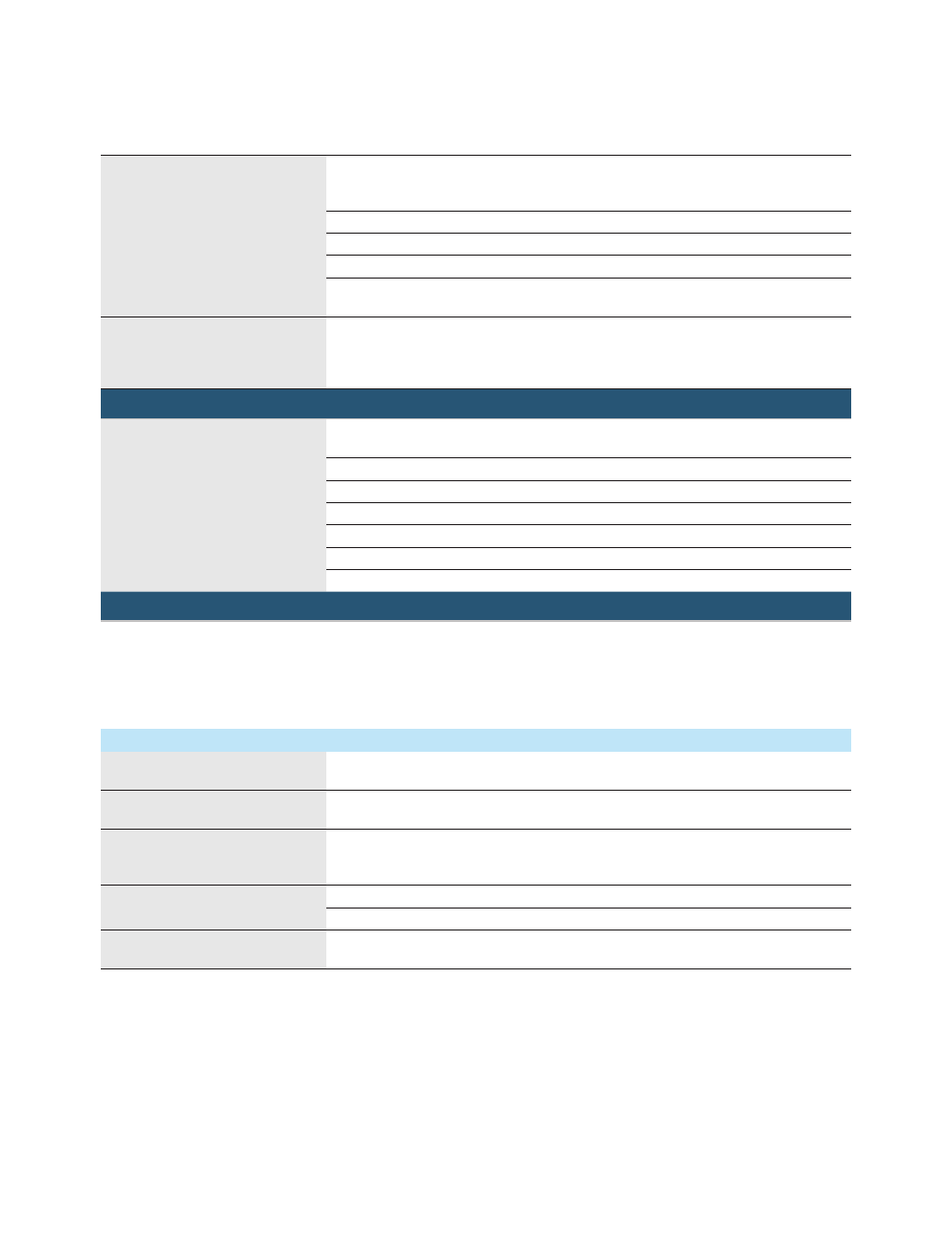
Markers
Markers are defined in a segment during the waveform generation process, or from the front
panel; a marker can also be routed to the RF blanking, ALC hold functions, and alternate
amplitude; see Users Guide for more information
Marker polarity
Negative, positive
Number of markers
4
RF blanking/burst on/off ratio
> 80 dB
Alternate amplitude control switching
speed
See amplitude section
Real-time modulation FIR filter:
Filter Types: Nyquist, root-Nyquist, WCDMA, EDGE, Gaussian, rectangular, APCO
25 C4FM, IS-95, User FIR
(Applies real-time FIR filtering when playing waveforms with OSR=1 . Helps reduce waveform
size for long simulation times . Option 660 not required .)
Real-time baseband generator (Option 660)
Real-time baseband generator required
for real-time Signal Studio
applications
1
Cellular real-time applications
LTE-FDD, LTE-TDD, HSPA+/W-CDMA, GSM/EDGE,
cdma2000
®
Real-time navigation
GPS, GLONASS, Galileo
Real-time video applications
DVB-T/T2/H/S/S2/C/J .83 Annex A/C, ISDB-T/
Note: Option 660 is not required for real-time custom modulation (Option 431)
Memory: Shares memory with Options 656 and 657
Triggering: Same as Options 656 and 657
Markers: 3 markers available, all other features are same as Options 656 and 657
Digital baseband inputs/outputs (Option 003/004)
Options 003 and 004 activate the rear panel digital I/Q bus and enable connectivity to the N5102A digital signal interface module . In
output mode (003), you can deliver realistic complex-modulated signals such as LTE, GPS, WLAN, custom pulses and many others
directly to your digital devices and subsystems . In the input mode (004), the interface module ports your digital input to the signal
generator's baseband system, providing a quick and easy way of upconverting to calibrated analog I/Q, IF, or RF frequencies . In
both operating modes, the interface module adapts to your device with the logic type, data format, clock features, and signaling you
require .
Data (requires N5102A)
Digital data format
User-selectable: 2's complement or binary offset, IQ (I, I-bar, Q, Q-bar) or digital IF output
(real, imaginary)
Data port
Dual 16-bit data buses support parallel, parallel IQ interleaved, parallel QI interleaved, or
serial port configuration
N5102A connectors (breakout boards) 144-pin Tyco Z-Dok+ connects to break-out boards (included with N5102A) that interface
with the following connector types: 68-pin SCSI, 38-pin dual AMP Mictor, 100-pin dual
Samtec, 20-pin dual 0 .1 inch headers, 40-pin dual 0 .1 inch headers
Logic types
Single-ended: LVTTL, 1 .5V CMOS, 1 .8V CMOS, 2 .5V CMOS, 3 .3 .V CMOS
Differential: LVDS
Data output resampling
MXG baseband output is resampled to the arbitrary clock rate set by the user via real-time
curve-fit calculations .
1. See www.agilent.com/find/signalstudio for more information.