0 enclosure options, continued – Alpha Technologies UPE-6 User Manual
Page 34
34
031-124-C0-004, Rev. D
3.0
Enclosure Options, continued
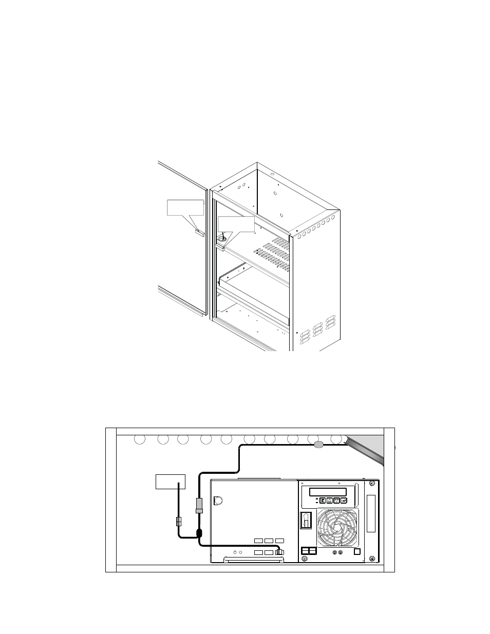
3.5 Enclosure Door Tamper Switch and Cooling Fan Options
Tamper Switch
The Tamper Switch is located on the edge of the power supply shelf, opposite the power
supply. The switches are available in Normally Closed (Alpha P/N 740-216-21) and Normally
Open (Alpha P/N 740-216-26). The USM2, USM-2.5, or DSM options are required to monitor
the Tamper Switch. The connector attached to the sensor portion of the switch must be
connected to the TMPR connection on the USM or DSM card.
Enclosure Cooling Fan
An optional Cooling Fan Kit (Alpha P/N 745-101-22) is available for the UPE-3 and UPE-6.
The fan is thermostatically controlled, and powered by the XM Series 2 power supply.
Fig. 3-5, Tamper Switch Placement
Fig. 3-6, Cooling Fan Placement
Tamper Switch
Magnet
Tamper Switch
Sensor
SPI
Thermostat
Fuse