3 battery heater mat, 4 lri-aci lamp option, 0 enclosure options, continued – Alpha Technologies UPE-6 User Manual
Page 33
33
031-124-C0-004, Rev. D
3.0
Enclosure Options, continued
3.3 Battery Heater Mat
Battery heater mats are designed to increase battery capacity in cold environments. The
thermostat is factory set to turn the mat on at 40ºF (4.44ºC), and off as the temp rises above
50ºF (10ºC). As a safety feature, the mat has a thermal fuse that opens at 180ºF (82.22ºC) to
protect the batteries from overheating. To install the mats:
1. Remove the batteries from the tray(s).
2. Place the heater mat in the bottom of the tray(s).
3. Replace the batteries.
4. Plug the AC line cord into the closest receptacle.
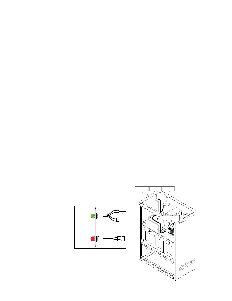
3.4 LRI-ACI Lamp Option
LRI Option
The LRI lamp (red lamp) is located on the outside, on either the right or left side of the
enclosure. The lamp comes ON only when the power supply is running on backup power
(STANDBY). During normal AC line operation, the lamp remains OFF. Whenever a fault is
detected, the lamp fl ashes to indicate that service is required. The LRI can be used as a
simple form of status monitoring by allowing cable technicians to check the operational status
of the power supply without having to open the enclosure. Connect the LRI lamp to the jack
on the front of the power supply labeled LRI.
ACI Option
The AC indicator (green lamp) is located on the outside, on either the right or left of the
enclosure. When the lamp is ON, it indicates AC power is available at the power supply
output (normal operation). This allows a cable technician to drive by and determine the
status of the power supply without having to open the enclosure. Connect one connector of
the ACI lamp to the OUTPUT 1 jack on the front of the power supply, and the other to the SPI.
Fig. 3-4, ACI/LRI Wiring
'LRI'
'Output 1'
LRI Lamp
ACI Lamp
SPI
BLK
RED
LRI Lamp
ACI Lamp
Enclosure
Wall
BLK
WHT
BLK
WHT