5 enclosure grounding – Alpha Technologies UPE-6 User Manual
Page 16
16
031-124-C0-004, Rev. D
2.0 Installation,
continued
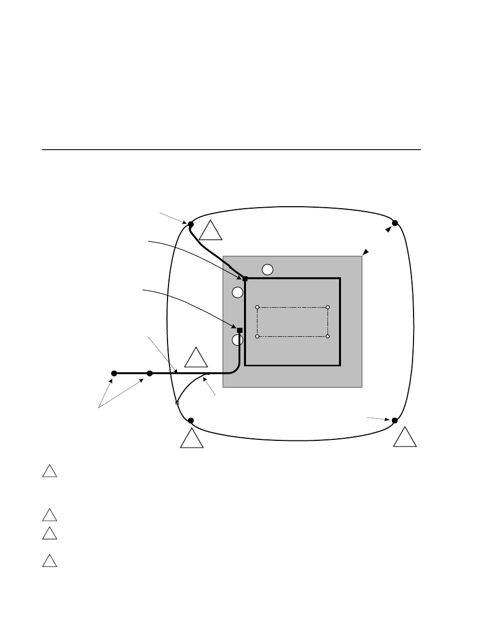
2.5 Enclosure
Grounding
Alpha recommends 5 ohm minimum ground resistance between enclosure and ground rods,
in accordance with IEEE 1100-1999, Powering and Grounding Electronic Equipment.
Alpha Technologies assumes no responsibility or liability for failure of the installer to comply
with the requirements of applicable local and national codes. Where allowed, exothermic
welding may be used as an alternative to Burndy clamps and connectors.
Alpha Technologies recommends using the grounding method illustrated below. The grounding method for a
particular site will be dependant upon soil type, available space, local codes, NEC (National Electric Code),
and other site-specifi c characteristics.
ATTENTION:
E nc los ure
F ootprint
1
2
3
4
Service Grounding (required)
1
#6 bare copper wire from Service Neutral / Ground Bar with 2 ground rods located 6’ (1.8m) apart.
Lightning Protection (optional)
2
1/2" x 8' (2.4m) copper ground rod, four places, driven about 2' (0.6m) (typical) from the corners of the pad.
3
#6 bare copper wire loop terminated to each ground rod and buried below grade 30" (9.1m) (min).
Corrosion-proof connections (25+ year life-span), and hardware suitable for direct burial MUST be used.
4
#6 bare copper wire from loop to the enclosure.
2' min.
Connection made with Burndy
connector (P/N YG HR58 C2W-3
or equivalent)
Terminate at enclosure ground
Terminate at service
entrance ground
#6AWG
Two 8' (2.4m) ground rods, 6' (1.8m)
apart, min.
(may require additional ground rods to meet NEC
minimum grounding standard of 25 ohms or less)
Connection made with Burndy connector
(P/N YGHP58C2W-2TN or equivalent)
#2AWG