7 coaxial cable connection – Alpha Technologies UPE-6 User Manual
Page 22
22
031-124-C0-004, Rev. D
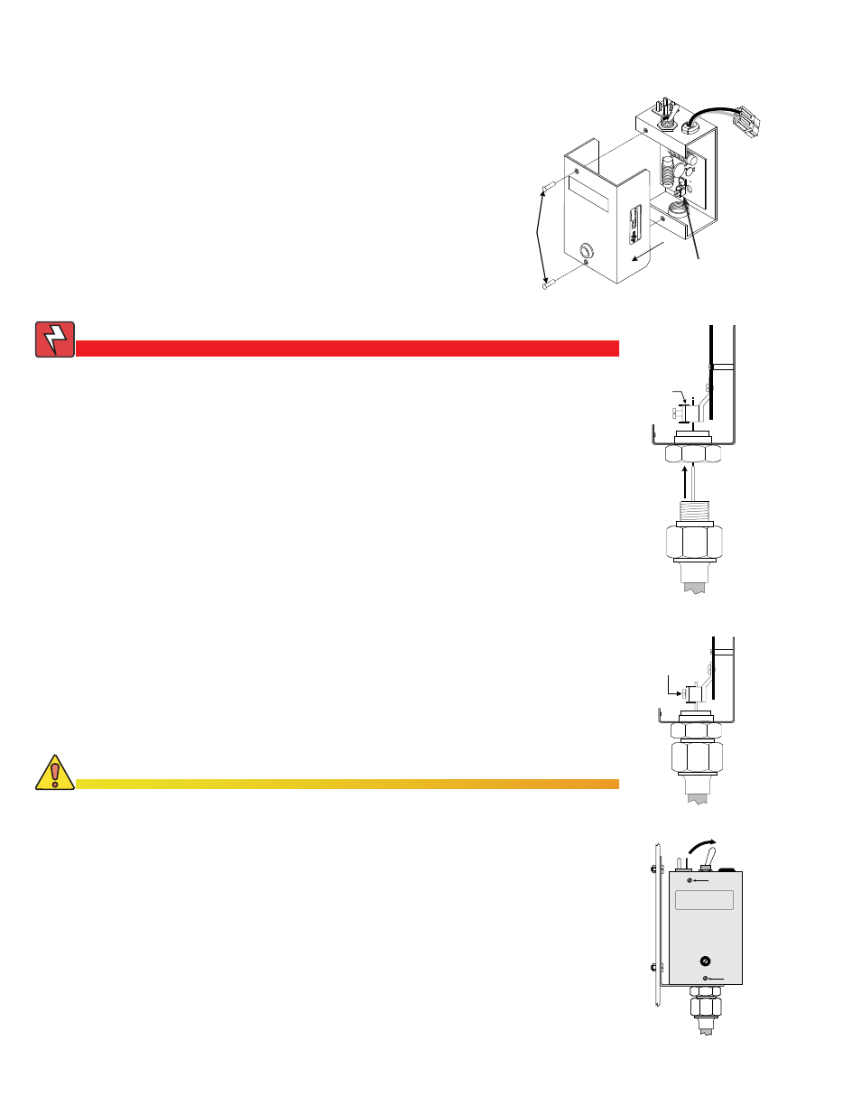
5. Tighten the seizure screw to 35 in-lbs (4 Nm).
4. Insert the coaxial termination into the output port
on the bottom of the SPI and tighten snug.
6. Replace the SPI’s cover and reinstall the screws.
7. Verify the switch on the top of the SPI is in the ON position.
To prevent arcing, and failure of the unit, the center conductor (stinger) of the
coaxial termination must go fully inside the seizure screw assembly.
2.0 Installation,
continued
2.7 Coaxial Cable Connection
1. Do NOT remove SPI cover until all sources of
power have been removed. Verify the SPI is not
connected to power supply.
2. Remove the two screws holding the cover onto the
SPI’s chassis.
3. Remove the SPI cover, exposing the circuit board
and seizure screw assembly.
WARNING!
Verify there is no power to the SPI before removing the outer cover.
Failure to do so may expose the technician to hazardous voltages.
5
ALT ON
7
6
6
CAUTION!
2
3
1
Seizure Screw
Assembly
Seizure
Screw
4
Seizure Screw
Assembly
Output
Port
Stinger
Circuit
Board
Coaxial
Termination