2 verifying correct hardware interconnection, 0 start up and verification – Alpha Technologies DSM3 for XM3 - Technical Manual User Manual
Page 82
82
745-814-B11-001, Rev. C (03/2014)
9.2
Verifying Correct Hardware Interconnection
The BAT A/B and BAT C/D LED indicators on the front panel of the DSM3 Series unit should illuminate
solid green once the battery wiring harnesses are correctly installed. A system with multiple strings must
use String A as the first string, B as the second, C as the third and D as the fourth.
The DSM3x model provides both BAT A/B and BAT C/D LED indicators and battery harness connectors
(supports a maximum 4 battery strings). The DSM3 model provides only the BAT A/B LED indicator and
battery harness connector (supports a maximum 2 battery strings).
NOTE:
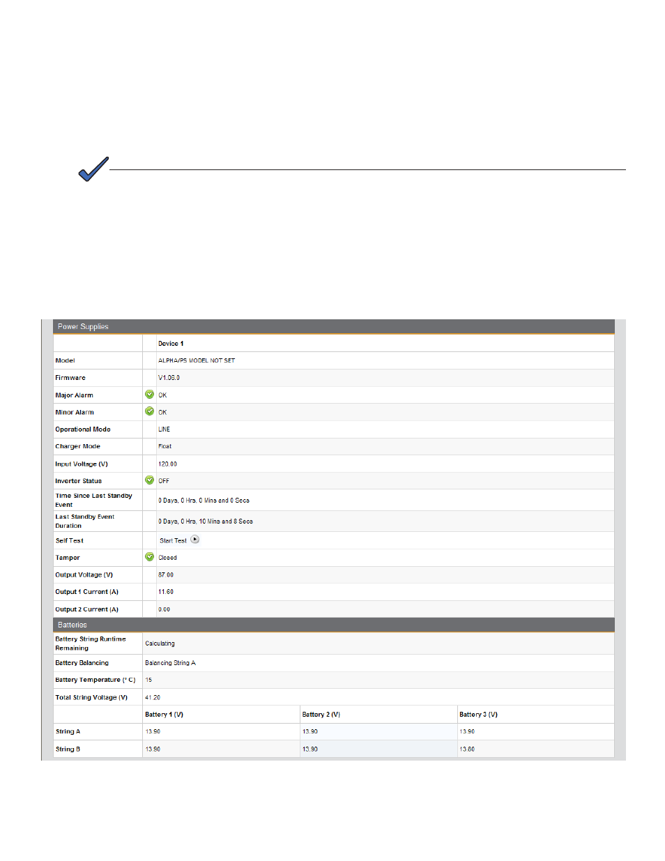
From the Power Supplies and Batteries section of
General tab of the DSM3 Series Web page, the
following screen will be visible and the parameters shown will be available for viewing and verification.
To test hardware interconnection using the Ethernet port, verify valid values for Output Voltage, Output
Current and individual battery voltages.
Fig. 9-3, Power Supply Section - General Page
9.0 Start Up and Verification