Table 7-1, tamper (tpr) switch specifications, 8 i/o connections (tpr, env), 1 tamper (tpr) switch interface – Alpha Technologies DSM3 for XM3 - Technical Manual User Manual
Page 71: 0 installation
71
745-814-B11-001, Rev. C (03/2014)
7.0 Installation
7.8
I/O Connections (TPR, ENV)
The Alpha DSM3 series transponders (DSM3, DSM3x, DPM) are all populated with a Tamper interface to
report the status of the power supply enclosure door when equipped with the optional tamper switch. The
Alpha DSM3x and DPM are populated with the Environmental and I/O Controller interface (referred to in
this section as I/O Port) which can be used to monitor and control an array of contact relay devices such
as battery heater mats, enclosure moisture sensors and emergency generators.
7.8.1 Tamper (TPR) Switch Interface
The tamper switch interface is designed to report and alarm the status of the power supply
enclosure door. The circuit created by the tamper switch is a contact relay, so other contact relay
devices can be designed to be monitored through this interface. For example, the Alpha Utility
Line Sensor (Alpha P/N 746-399-2X) uses the tamper interface to monitor the Utility outlet to
report the presence of line voltage.
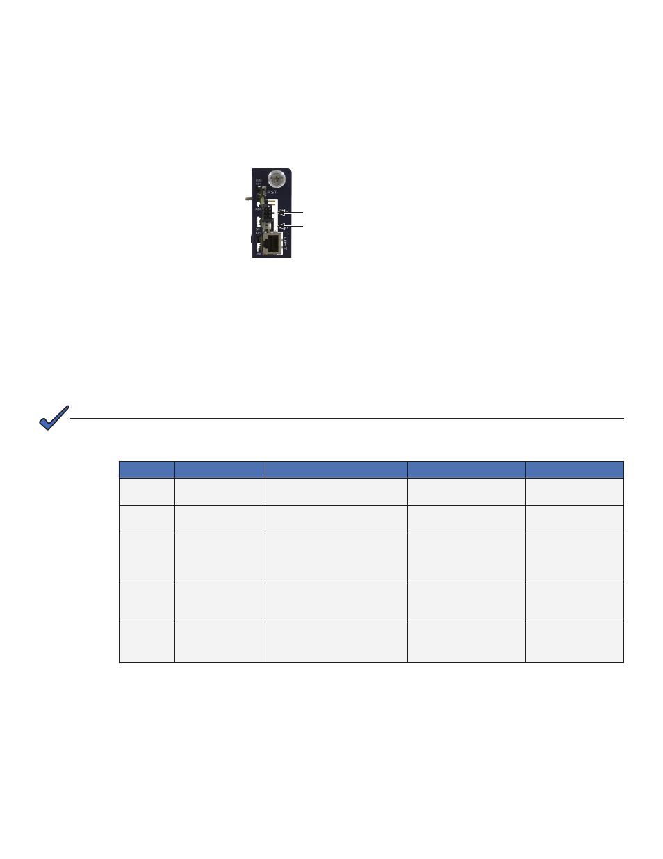
Fig. 7-9, I/O (ENV) and Tamper Switch Interface (TPR) Connection Locations
I/O Control Interface (ENV)
Tamper Switch Interface (TPR)
Table 7-1, Tamper (TPR) Switch Specifications
Function
Parameter
OID
Values
Description
Tamper
psTamper
1.3.6.1.4.1.5591.1.4.2.1.27.X
See Note 1
1 = Closed
2 = Open
Status of enclosure
door
Utility
Sense
psTamper
1.3.6.1.4.1.5591.1.4.2.1.27.X
1 = No Voltage
2 = Voltage present
Status of Utility
Voltage
tamperPolarity
1.3.6.1.4.1.926.1.3.2.6.1.0
1 = Report “Open” when
contact open
2 = Report “Open” when
contact closed
Controls polarity of
‘psTamper’ reporting
Alarm/
Trap
psTamper(Closed) 1.3.6.1.4.1.5591.1.1.3.1.3.13.1
.3.6.1.4.1.5591.1.4.2.1.27.X.1
1 = disable
2 = enableMajor
3 = enableMinor
Alarm enable for
psTamper=”Closed”
Alarm/
Trap
psTamper(Open)
1.3.6.1.4.1.5591.1.1.3.1.3.13.1
.3.6.1.4.1.5591.1.4.2.1.27.X.2
1 = disable
2 = enableMajor
3 = enableMinor
Alarm enable for
psTamper=”Open”
In the OID column of the following table, ‘X’ denotes power supply device address (Default = 1)
NOTE: